
Frequency domain mosaic microscopy system based on spatial light modulator

A spatial light modulator and microscopic system technology, applied in microscopes, instruments, optics, etc., can solve problems such as low resolution, slow mechanical scanning speed, and lack of acquisition at the imaging end, achieving improved spatial resolution and flexible programming The effect of controlling and improving the collection speed

Active Publication Date: 2019-07-26
TSINGHUA UNIV
View PDF6 Cites 0 Cited by
  • Summary
  • Abstract
  • Description
  • Claims
  • Application Information

AI Technical Summary

Problems solved by technology

In short, the disadvantage of the FPM system at the illumination end based on the LED array is that this system is only suitable for very thin transparent or translucent samples, because the variable light based on the LED array is modulated on the incident surface of the sample, if the sample If it is too thick, when passing through the sample, the wavefront will be changed at different depths of the sample. The outgoing wave is equivalent to the incident wave convolving the depth information of multiple layers of the sample, and the imaging end will not be able to collect the correct modulated image at the incident end.
On the other hand, the shortcomings of the FPM system at the acquisition end based on mechanical scanning are: (1) The illumination end of the system is a constant parallel light, so the resolution is limited by the NA of the objective lens. , can use a sensor with poor performance and low resolution to take high-resolution images; (2) The mechanical scanning speed controlled by the controller is slow, and the scanning method cannot be flexibly controlled, especially multi-aperture Multiplex acquisition of
However, the convergence and algorithm efficiency of the algorithm are poor, and the sensitivity to sample collection data is high.

Method used


Image

  • Frequency domain mosaic microscopy system based on spatial light modulator
  • Frequency domain mosaic microscopy system based on spatial light modulator
  • Frequency domain mosaic microscopy system based on spatial light modulator

Examples


Embodiment Construction

[0032] Embodiments of the present invention are described in detail below, examples of which are shown in the drawings, wherein the same or similar reference numerals designate the same or similar elements or elements having the same or similar functions throughout. The embodiments described below by referring to the figures are exemplary only for explaining the present invention and should not be construed as limiting the present invention.

[0033] In describing the present invention, it should be understood that the terms "center", "longitudinal", "transverse", "upper", "lower", "front", "rear", "left", "right", " The orientations or positional relationships indicated by "vertical", "horizontal", "top", "bottom", "inner" and "outer" are based on the orientations or positional relationships shown in the drawings, and are only for the convenience of describing the present invention and Simplified descriptions, rather than indicating or implying that the device or element refe...


PUM


Abstract

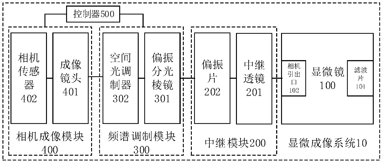
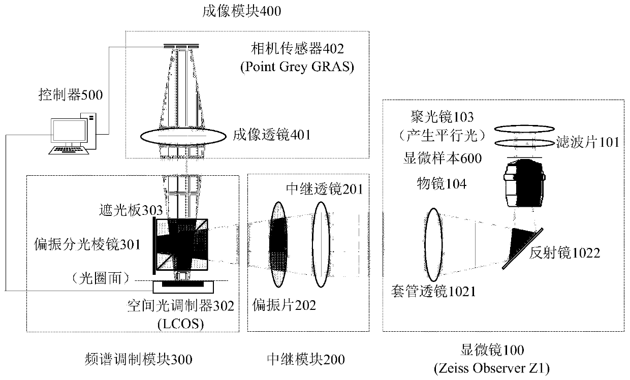
The present invention provides a collection end frequency domain pasting microscopic system based on a spatial light modulator. The system comprises: a microscope configured to amplify a microscopic sample into an image plane; a relay module configured to reduce the aperture plane of imaging of the sample; a frequency spectrum modulation module consisting of a polarization splitting prism and a spatial light modulator; a camera imaging module consisting of an imaging lens and a camera sensor and configured to receive optical signals through frequency spectrum modulation through the spatial light modulator and then through the emission through the slope of the polarization splitting prism and collect the corresponding sample image; a controller configured to perform synchronous control of frequency spectrum modulation and image collection and rapidly collect a plurality of low-resolution images in different spatial frequency spectrums to obtain an original image data required by the single-frame high-resolution images or the multi-frame high-resolution video. On the premise of ensuring the field of view with a certain width, the spatial resolution collected by the camera sensor is improved, the high-resolution reconstruction with a certain thickness sample is realized, the collection of the dynamic samples is realized to some extent, and the collection end frequency domain pasting microscopic system based on the spatial light modulator is simple and easy to realize.

Description

technical field [0001] The invention relates to the technical field of microscopic imaging, in particular to a frequency-domain mosaic microsystem based on a spatial light modulator. Background technique [0002] FPM (Fourier Ptychography Microscopy, Frequency Domain Collage Microscopy) is a microscopic imaging method that can satisfy both wide field of view and high resolution. This method collects low-resolution sample images corresponding to different spatial frequencies, and collages these low-resolution microscopic images in the Fourier domain to restore the microscopic imaging method of wide-field high-resolution images. This method can also restore Phase information of the sample and 3D reconstruction of a certain thickness. This method can obtain a large spatial bandwidth product (Spatial Bandwidth Product, SPB), which breaks through the diffraction limit of the optical system to some extent, so it has important applications in optical bioimaging. [0003] At prese...

Claims


Application Information

Patent Timeline
Patent Type & Authority Patents(China)
IPC IPC(8): G02B21/36G02B21/00
CPCG02B21/002G02B21/361G02B21/365
Inventor 戴琼海周游吴嘉敏
Owner TSINGHUA UNIV
Learn More