
Ultra high speed light signal generator based on grapheme micro fibe

An ultra-high-speed, graphene technology, applied in instruments, optics, nonlinear optics, etc., can solve the problem that the modulation rate cannot exceed 1GHz, and achieve the effect of easy fabrication and low transmission loss

Active Publication Date: 2017-05-24
BEIJING JIAOTONG UNIV
View PDF3 Cites 0 Cited by
  • Summary
  • Abstract
  • Description
  • Claims
  • Application Information

AI Technical Summary

Problems solved by technology

But their parasitic capacitance makes the electronic circuit equivalent to an RC low-pass filter (3dB electric signal cut-off frequency f=1 / 2πRC, electronic bottleneck), so that the highest modulation rate in the experiment cannot break through the order of 1GHz, which is far lower than the simulation calculation The results (tens to hundreds of GHz)

Method used


Image

  • Ultra high speed light signal generator based on grapheme micro fibe
  • Ultra high speed light signal generator based on grapheme micro fibe
  • Ultra high speed light signal generator based on grapheme micro fibe

Examples


Embodiment 1

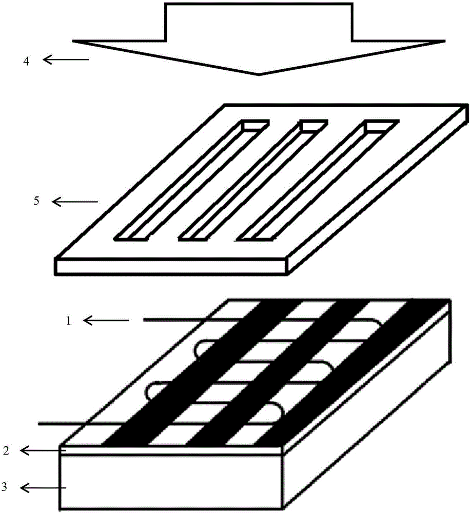
[0044]The ultra-high-speed optical signal generator based on graphene micro-fiber is characterized in that the structure includes a micro-fiber 1, a graphene layer 2, a flat substrate 3, a pump light source 4 and a mask plate 5.

[0045] The specific combination method is: the graphene layer 2 is placed on the flat substrate 3, the microfiber 1 is placed on the graphene layer 2 in a coiled manner, and the pump light generated by the pump light source 4 passes through the mask plate 5 to generate diffraction fringes for irradiation. On the graphene layer 2, the intensity of the pumping light is changed to adjust the absorption characteristics of the graphene layer 2 to the carrier to generate an ultra-high-speed optical signal.

[0046] The thickness of the graphene layer 2 is less than 3.35nm.

[0047] The diameter of the fine optical fiber 1 is 1 μm, the parallel spacing between the coils of the fine optical fiber 1 is 1 mm, and the total length is 37 mm.

[0048] The genera...

Embodiment 2

[0051] The ultra-high-speed optical signal generator based on graphene micro-fiber is characterized in that the structure includes a micro-fiber 1, a graphene layer 2, a flat substrate 3, a pump light source 4 and a mask plate 5.

[0052] The specific combination method is: the graphene layer 2 is placed on the flat substrate 3, the microfiber 1 is placed on the graphene layer 2 in a coiled manner, and the pump light generated by the pump light source 4 passes through the mask plate 5 to generate diffraction fringes for irradiation. On the graphene layer 2, the intensity of the pumping light is changed to adjust the absorption characteristics of the graphene layer 2 to the carrier to generate an ultra-high-speed optical signal.

[0053] The thickness of the graphene layer 2 is less than 3.35nm.

[0054] The diameter of the fine optical fiber 1 is 1 μm, the parallel spacing between the coils of the fine optical fiber 1 is 1 mm, and the total length is 37 mm.

[0055] The gener...


PUM

PropertyMeasurementUnit
thicknessaaaaaaaaaa
diameteraaaaaaaaaa

Abstract

The invention discloses an ultra high speed light signal generator based on grapheme micro fiber which comprises: the microfiber, the grapheme layer, the flat base, the pump light and the mask plate. The concrete combinations way comprises: the grapheme layer is set on the flat base, the microfiber is set on the grapheme layer in the form of the coiling, the mask plate is set on the grapheme layer, the pump light is set on the mask plate; the pump light from the pump source generates diffraction fringe through the mask plate on the graphene layer, the absorption characteristics of the carrier is adjusted by changing the intensity of the pump light to produce a super speed light signal.

Description

technical field [0001] The invention belongs to the field of optical fiber devices for communication, in particular to an ultra-high-speed signal generator based on graphene microfibers. Background technique [0002] Electro-optic / photoelectric conversion is a key factor restricting high-speed communication systems. The use of all-optical control methods can effectively bypass the parasitic capacitance effect (electronic bottleneck) of electronic devices at ultra-high frequencies and improve communication speed. At the same time, the all-optical control method plays an irreplaceable role in optical logic computing. [0003] OTDM (Optical Time Division Multiplexing Technology) adopts delay technology to delay and multiplex low-speed optical signals to form ultra-high-speed optical signals, which can realize ultra-high-speed communication in a single channel, and is the main technology supporting the main body of modern communication backbone networks . Existing optical time...

Claims


Application Information

Patent Timeline
Patent Type & Authority Applications(China)
IPC IPC(8): G02F1/035
CPCG02F1/035
Inventor 裴丽白冰
Owner BEIJING JIAOTONG UNIV
Learn More