Air-cooling three-phase oil-immersed distribution transformer

An oil-immersed technology for distribution transformers, applied in the field of transformers, can solve problems such as high sealing performance requirements, potential safety hazards, and difficulty in realization, and achieve the effects of increasing heat dissipation rate, improving heat dissipation and cooling efficiency, and facilitating self-radiation

Inactive Publication Date: 2017-05-24
江苏凡高电气有限公司
View PDF13 Cites 1 Cited by
  • Summary
  • Abstract
  • Description
  • Claims
  • Application Information

AI Technical Summary

Problems solved by technology

However, the spiral pipe used for heat exchange in this technical solution is placed inside the transformer oil tank, and its mechanism is complicated and difficult to realize. Explosive substances, if the sealing measures are not done well, there will be potential safety hazards

Method used


Image

  • Air-cooling three-phase oil-immersed distribution transformer
  • Air-cooling three-phase oil-immersed distribution transformer
  • Air-cooling three-phase oil-immersed distribution transformer

Examples


Embodiment 1

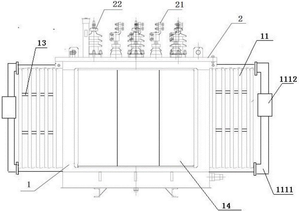
[0030] Figure 1 to Figure 4 It schematically shows that a forced guiding cooling three-phase oil-immersed distribution transformer is provided according to the first embodiment of the present invention.

[0031] Such as figure 1 As shown, the present invention discloses a forced-guided cooling three-phase oil-immersed distribution transformer, which includes an oil tank 1, and a transformer core is installed in the oil tank 1. At the same time, the oil tank 1 is filled with high-temperature resistant insulating oil. In this embodiment of the invention Among them, the high-temperature-resistant insulating oil is β liquid, and silicone oil FR3 natural ester can also be used in practical applications. The transformer core is immersed in high temperature resistant insulating oil.

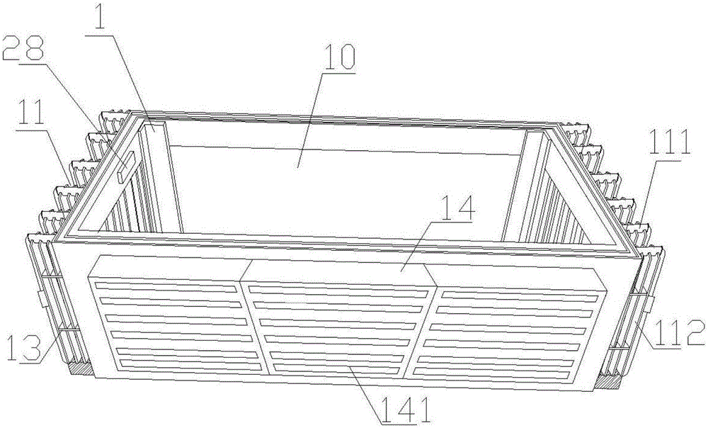
[0032] Such as Figure 1 to Figure 4 As shown, preferably, in this embodiment of the present invention, the oil tank 1 adopts a corrugated oil tank, such as image 3 As shown, the oil tank 1 is a h...

Embodiment 2

[0041] Figure 1 to Figure 6 It schematically shows that a forced guiding cooling three-phase oil-immersed distribution transformer is provided according to the second embodiment of the present invention.

[0042] Such as Figure 1 to Figure 4 As shown, the second embodiment of the present invention discloses a forced-guided cooling three-phase oil-immersed distribution transformer which is basically the same as Embodiment 1, except that:

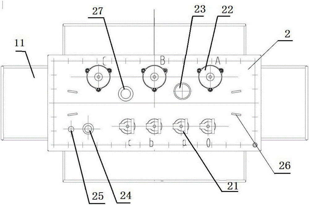
[0043] Such as figure 2 , image 3 , Figure 5 and Figure 6 As shown, as another invention point of the present invention, in this embodiment of the present invention, a control system for controlling the fuel tank in the fuel tank 1 is included, the control system includes a liquid level sensor 28 fixed on the inner wall of the fuel tank 1, and A controller 27 above the cover 2, and the liquid level sensor 28 is connected with the controller 27. Such as figure 2 As shown, the liquid level sensor 28 is fixed on the upper end of on...


PUM


Abstract

The invention provides an air-cooling three-phase oil-immersed distribution transformer. The air-cooling three-phase oil-immersed distribution transformer comprises a transformer body. The transformer body comprises an oil box. The oil box is filled with high temperature resistant insulating oil. A transformer core is installed in the oil box, and the transformer core is immersed in the high temperature resistant insulating oil. At least one side wall of the oil box is communicated with a ripple tank. One side of the ripple tank is provided with a cooling fan of the ripple tank. The air outlet of the cooling fan of the ripple tank faces to the interior of the oil box. The provided air-cooling three-phase oil-immersed distribution transformer is capable of, through the cooling fan installed under the ripple tank, improving the cooling rate of the high temperature resistant insulating oil in the ripple tank, and further improving the heat-radiating cooling efficiency of the transformer through a cooling fan installed on the side face of the oil box. In addition, the back face of the cooling fan of the oil box is further provided with a self-cooling grating convenient for the self-cooling of the cooling fan of the oil box.

Description

technical field [0001] The invention relates to the technical field of transformers, in particular to an air-cooled three-phase oil-immersed distribution transformer with improved heat dissipation performance. Background technique [0002] Transformer is an important equipment in power generation, power supply and power consumption enterprises. It is also in a very critical position in the power grid. It is an important device to ensure the safe and reliable operation of the power grid and the electrodes used by people in production and life. [0003] Oil-immersed transformers are suitable for power systems, industrial and mining enterprises, transportation, post and telecommunications departments, scientific research units, etc., to conduct dielectric strength tests on various high-voltage electrical equipment, electrical components, and insulating materials under power frequency or DC high voltage. Oil-immersed transformers rely on oil as the cooling medium, such as oil-im...

Claims


Application Information

Patent Timeline
Patent Type & Authority Applications(China)
IPC IPC(8): H01F27/08H01F27/14H01F27/22H01F27/40
CPCH01F27/085H01F27/14H01F27/22H01F27/402H01F2027/404
Inventor 朱万盛钱蓉蓉管生立
Owner 江苏凡高电气有限公司
Why Eureka
Try Eureka