Cooling circulation process for fuel cell
A fuel cell and cooling cycle technology, which is applied in the direction of fuel cells, fuel cell additives, fuel cell heat exchange, etc., can solve the problems that are not ideal, and the energy conversion efficiency of the cooling cycle cannot be selected in stages, so as to achieve high energy conversion efficiency Effect
- Summary
- Abstract
- Description
- Claims
- Application Information
AI Technical Summary
Problems solved by technology
Method used
Image

Examples
Embodiment 1
[0056] Example 1 The stationary proton exchange membrane fuel cell adopting the cooling circulation process of the present invention
[0057] This embodiment uses a 10kW water-cooled proton exchange membrane fuel cell stack with 120 single cells.
[0058] In this embodiment, the fuel cell low temperature alarm temperature point and the fuel cell high temperature alarm temperature point are 50° C. and 65° C. respectively.
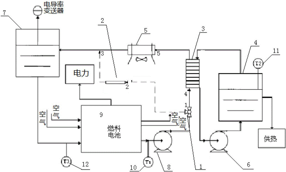
[0059] First, the gas line is purged with nitrogen. Then supply hydrogen and air to the poles of the fuel cell respectively, and start the fuel cell and its auxiliary machines (including the circulation pump). Next, the temperature T1 of the water outlet of the fuel cell, the temperature T2 of the heat exchange circulating water, and the temperature T3 of the water inlet of the fuel cell are detected. When the temperature T1 is lower than 50° C., the second circulation pump is started, and the first circulation pump and the fan of the radiator are not star...
Embodiment 2
[0060] Example 2 Direct Methanol Fuel Cell Using the Cooling Circulation Process of the Present Invention
[0061] This embodiment uses a 5kW water-cooled direct methanol fuel cell stack with 60 single cells.
[0062] First, the gas line is purged with nitrogen. Then supply methanol and air to the two poles of the fuel cell, and start the fuel cell and its auxiliary machines (including the circulation pump). Next, the temperature T1 of the water outlet of the fuel cell, the temperature T2 of the heat exchange circulating water, and the temperature T3 of the water inlet of the fuel cell are detected. When the temperature T1 is lower than 120° C., the second circulation pump and the ion column are started, and the first circulation pump and the fan of the radiator are not started. When the temperature T1 is higher than 120° C. and lower than 135° C., the first circulation pump is activated, but the radiator is not activated. As the temperature T1 gradually increases, the speed...
Embodiment 3
[0063] Example 3 High temperature solid oxide fuel cell using the cooling cycle process of the present invention
[0064] This embodiment uses a 30kW high temperature solid oxide fuel cell stack with 350 single cells.
[0065] First, the gas line is purged with nitrogen. Then supply hydrogen and air to the poles of the fuel cell respectively, and start the fuel cell and its auxiliary machines (including the circulation pump). Next, the temperature T1 of the water outlet of the fuel cell, the temperature T2 of the heat exchange circulating water, and the temperature T3 of the water inlet of the fuel cell are detected. When the temperature T1 is lower than 800° C., the second circulation pump is started, and the first circulation pump and the fan of the radiator are not started. When the temperature T1 is higher than 800° C. and lower than 830° C., the first circulation pump is activated, but the radiator is not activated. As the temperature T1 gradually increases, the speed o...
PUM
 Abstract
Description
Claims
Application Information
 - R&D
- Intellectual Property
- Life Sciences
- Materials
- Tech Scout
- Unparalleled Data Quality
- Higher Quality Content
- 60% Fewer Hallucinations
Browse by: Latest US Patents, China's latest patents, Technical Efficacy Thesaurus, Application Domain, Technology Topic, Popular Technical Reports.
© 2025 PatSnap. All rights reserved.Legal|Privacy policy|Modern Slavery Act Transparency Statement|Sitemap|About US| Contact US: help@patsnap.com