Adsorbing condensing type oil vapor recovery device for effectively preventing adsorption temperature rise and oil vapor recovery method

A recovery device and condensing technology, applied in the field of adsorption condensation oil and gas recovery devices, can solve problems such as increasing energy consumption, increasing investment, and increasing system complexity.

Active Publication Date: 2017-05-31
上海聚宸新能源科技有限公司
View PDF5 Cites 9 Cited by
  • Summary
  • Abstract
  • Description
  • Claims
  • Application Information

AI Technical Summary

Problems solved by technology

This will undoubtedly increase investment and increase system complexity
[0010] On the other hand, after activated carbon absorbs oil and gas, the activated carbon is generally regenerated by vacuum regeneration process. During regeneration, the adsorbent will cool down due to the volatilization of adsorbed oil and gas, and the lower temperature will make it difficult to desorb oil and gas.
What's more serious is that for some high melting point substances such as benzene, due to evaporation and heat absorption during desorption, t

Method used


Image

  • Adsorbing condensing type oil vapor recovery device for effectively preventing adsorption temperature rise and oil vapor recovery method
  • Adsorbing condensing type oil vapor recovery device for effectively preventing adsorption temperature rise and oil vapor recovery method
  • Adsorbing condensing type oil vapor recovery device for effectively preventing adsorption temperature rise and oil vapor recovery method

Examples


Embodiment 1

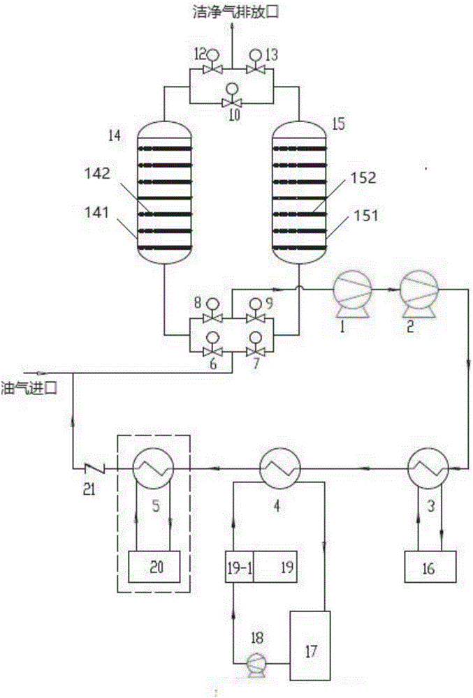
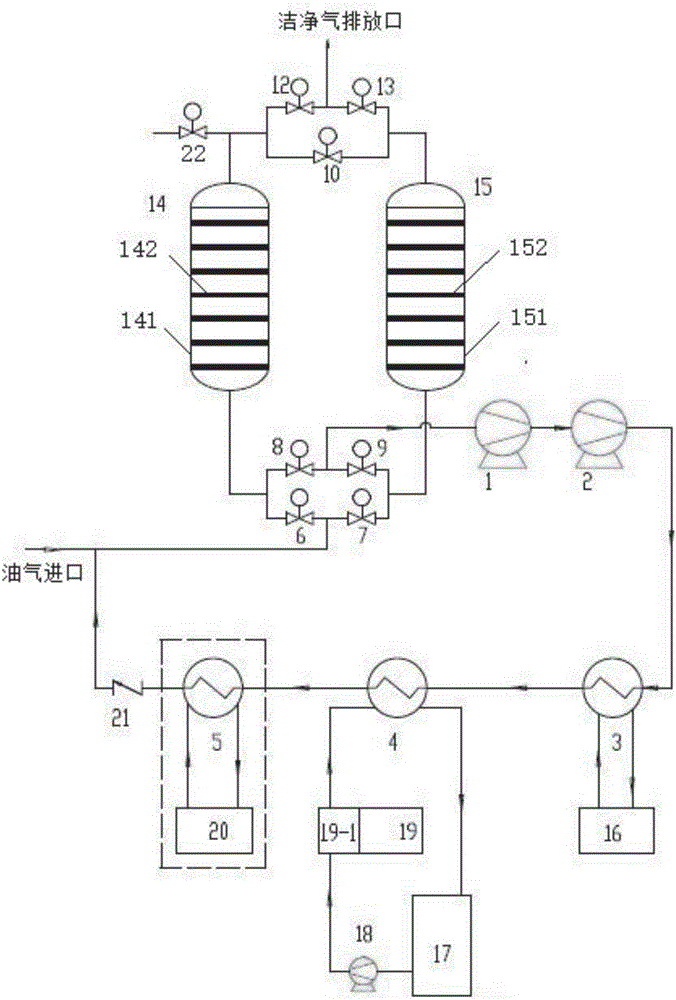
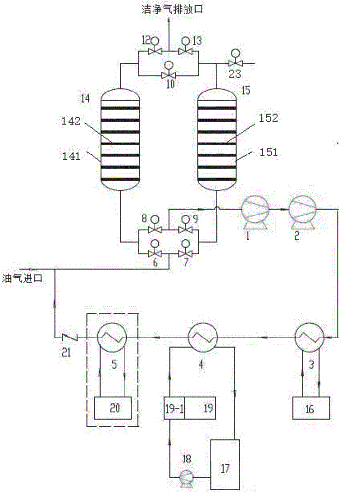
[0131] Such as Figure 1-5 As shown, the present invention discloses an adsorption condensation type oil gas recovery device that can effectively prevent adsorption temperature rise, including oil gas inlet, first valve group, adsorption tank group, second valve group, clean gas discharge port, vacuum pump group, first stage Oil-gas condenser 3, secondary oil-gas condenser 4, tertiary oil-gas condenser 5 and check valve 21, wherein:

[0132] The first valve group is composed of an intake valve group and a vacuum valve group connected in parallel below the adsorption tank group;

[0133] The second valve group is composed of an exhaust valve group located above the adsorption tank group and a purge valve group connected in parallel;

[0134] The purge valve group, the adsorption tank group, the vacuum valve group, the vacuum pump group, the first-stage oil-gas condenser 3, the second-stage oil-gas condenser 4, the third-stage oil-gas condenser 5 and the check valve 21 are conn...

Embodiment 2

[0165] Such as Figure 9 As shown, the present invention also discloses an adsorption condensation oil gas recovery method that effectively prevents the temperature rise of adsorption, comprising the following steps:

[0166] Step 1: The oil and gas to be treated enter through the oil and gas inlet, mix with a very small amount of uncondensed oil and gas discharged from the oil and gas condensing system (first-stage oil-gas condenser 3, second-stage oil-gas condenser 4 and third-stage oil-gas condenser 5), and then pass through the inlet The gas valve group enters the corresponding activated carbon adsorption tank, and the oil gas enters the left adsorption tank 14 through the left oil and gas inlet valve 6, and is adsorbed and intercepted by the first adsorbent in the left adsorption tank 14, and the solid-liquid phase change material absorbs a large amount of adsorption heat through the finned tube The solid-liquid phase change material is changed from solid to liquid, and t...

Embodiment 3

[0170] Such as Figure 10 As shown, the present invention additionally discloses an adsorption condensation oil gas recovery method that effectively prevents the temperature rise of adsorption, and is characterized in that it comprises the following steps:

[0171] Step A: The oil and gas to be treated enter through the oil and gas inlet, mix with a very small amount of uncondensed oil and gas discharged from the oil and gas condensing system (first-stage oil-gas condenser 3, second-stage oil-gas condenser 4 and third-stage oil-gas condenser 5), and then pass through the inlet The gas valve group enters the corresponding activated carbon adsorption tank, and the oil gas enters the right adsorption tank 15 through the right oil and gas inlet valve 7, and is adsorbed and intercepted by the second adsorbent in the right adsorption tank 15, and the solid-liquid phase change material absorbs a large amount of adsorption heat through the finned tube The solid-liquid phase change mat...


PUM

PropertyMeasurementUnit
Heat of phase changeaaaaaaaaaa
Densityaaaaaaaaaa

Abstract

The invention discloses an adsorbing condensing type oil vapor recovery device for effectively preventing adsorption temperature rise and an oil vapor recovery method. The device comprises an oil vapor inlet, a first valve set, an adsorption tank set, a second valve set, a clean gas exhaust port, a vacuum pump set, a first-level oil vapor condenser, a second-level oil vapor condenser, a third-level oil vapor condenser and a check valve, wherein the first valve set is composed of a gas inlet valve set under the adsorption tank set and a vacuum valve set in parallel connection with each other; the second valve set is composed of an exhaust valve set above the adsorption tank set and a blow-down valve set in parallel connection with each other; the blow-down valve set, the adsorption tank set, the vacuum valve set, the vacuum pump set, the first-level oil vapor condenser, the second-level oil vapor condenser, the third-level oil vapor condenser and the check valve are connected in turn; the check valve is connected with the oil vapor inlet; the oil vapor inlet is connected with the gas inlet valve set, the adsorption tank set, the exhaust valve set and the clean gas exhaust port in turn; a solid-liquid phase variable energy storage substance is filled into the adsorption tank set.

Description

technical field [0001] The invention relates to the technical field of oil and gas recovery, in particular to an adsorption condensation type oil and gas recovery device and an oil and gas recovery method that can effectively prevent adsorption temperature rise. Background technique [0002] Oil and gas is a kind of VOC (Volatile Organic Compounds, volatile organic compounds) gas, which is generally a mixture containing volatile organic gases and a large amount of non-condensable gases. [0003] The existing mainstream oil and gas recovery and treatment processes generally include condensation + adsorption process, compression condensation + membrane + adsorption process, adsorption + absorption process, etc. [0004] 1. Condensation + adsorption process. Before the oil and gas enter the adsorption system, they need to be condensed first, which reduces the temperature and concentration of the adsorption system and controls the temperature rise of the adsorption. However, the...

Claims


Application Information

Patent Timeline
IPC IPC(8): B01D53/00B01D53/02B01D5/00
CPCB01D5/0003B01D5/0036B01D5/0057B01D53/002B01D53/02B01D2257/7022B01D2258/02
Inventor 白爽
Owner 上海聚宸新能源科技有限公司
Why Eureka
Try Eureka