SCR urea solution mixer

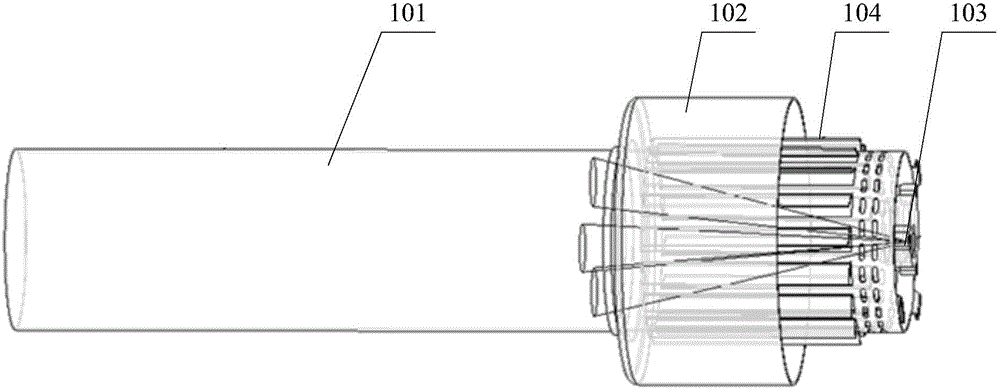
A solution mixing and urea technology, applied in fluid mixers, mixers, dissolving and other directions, can solve problems such as the deposition of urea mixing pipe 101, and achieve the effects of reducing excessive urea deposition, improving mixing, and promoting full utilization

Active Publication Date: 2017-05-31
WEICHAI POWER CO LTD
View PDF4 Cites 9 Cited by
  • Summary
  • Abstract
  • Description
  • Claims
  • Application Information

AI Technical Summary

Problems solved by technology

[0007] Although the above-mentioned technical scheme can improve the mixing uniformity of the urea solution by adding swirl sheets, it is unavoidable that the urea sprayed by the urea nozzle 103 will deposit on the inner wall of the urea mixing pipe 101

Method used


Image

  • SCR urea solution mixer
  • SCR urea solution mixer
  • SCR urea solution mixer

Examples


Embodiment Construction

[0034] The core of the present invention is to provide an SCR urea solution mixer to further reduce urea deposition.

[0035] Hereinafter, an embodiment will be described with reference to the drawings. In addition, the examples shown below do not limit the content of the invention described in the claims in any way. In addition, all the contents of the configurations shown in the following embodiments are not limited to be essential to the solutions of the invention described in the claims.

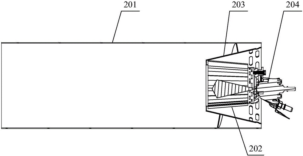
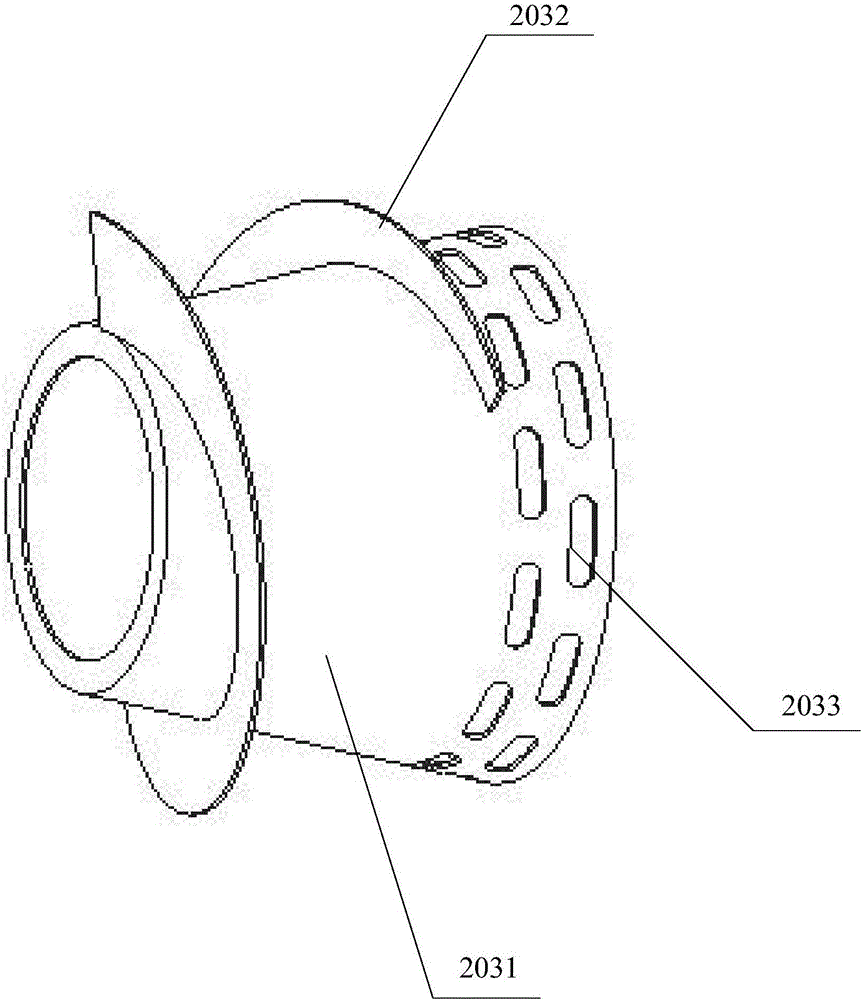
[0036] see figure 2 and Figure 5 , figure 2 The structural representation of the SCR urea solution mixer that the embodiment of the present invention provides, Figure 5 It is a side view of the inner tube provided by the embodiment of the present invention.

[0037] The embodiment of the present invention discloses an SCR urea solution mixer, which includes a urea mixing pipe 201 and a mixing assembly arranged inside one end of the urea mixing pipe 201 . Wherein, the mixing ass...


PUM


Abstract

The embodiment of the invention discloses an SCR urea solution mixer. The SCR urea solution mixer comprises a urea mixing pipe and a mixing assembly arranged in one end of the urea mixing pipe. The mixing assembly comprises an inner-layer pipe and an outer-layer pipe arranged on the outer side of the inner-layer pipe in a sleeving mode. A side wall hole is formed in the inner-layer pipe, and a spinning disk used for generating rotational flow is arranged on one side of the side wall hole. A spiral piece is arranged between the outer wall of the outer-layer pipe and the urea mixing pipe. Through the effect of the spiral piece, gas flow and rotation at the wall face position of the urea mixing pipe are accelerated, a urea liquid film thrown at the wall face position of the urea mixing pipe due to the strong rotational flow effect of the spinning disk is taken away in time, the urea crystallization risk is further reduced, and mixing of urea and airflow is improved. The SCR urea solution mixer can aim at engines with different displacements and different purposes, and the airflow volume can be reasonably distributed by adjusting the blade angles, lengths and numbers of the spinning disk and the spiral piece.

Description

technical field [0001] The invention relates to the technical field of mixers, in particular to an SCR urea solution mixer. Background technique [0002] The basic principle of SCR (Selective Catalytic Reduction, selective catalytic reduction technology) technology is to inject fuel or add other reducing agents to the exhaust, select a suitable catalyst, and promote the reduction of the reducing agent and NO x reaction while inhibiting the oxidation of the reducing agent by oxygen in the exhaust. According to the type of reducing agent, the existing SCR technology can be divided into NH produced by the decomposition of urea 3 There are two types of urea SCR technology as reducing agent and hydrocarbon SCR technology using hydrocarbon as reducing agent. At present, the hydrocarbon SCR technology is still under further research, and there are not many practical applications; while the urea SCR technology is relatively mature, and there are many practical applications. [00...

Claims


Application Information

Patent Timeline
Patent Type & Authority Applications(China)
IPC IPC(8): B01F5/00F01N3/20
CPCF01N3/2066B01F25/10B01F2101/25Y02T10/12
Inventor 王意宝张晓丽王东升王奉双张素英高伟
Owner WEICHAI POWER CO LTD
Why Eureka
Try Eureka