

Welding method and welding structure of lithium ion battery covers
A lithium-ion battery, welding method technology, applied in welding/welding/cutting items, battery caps/end caps, secondary batteries, etc., can solve the problems of difficult and precise control, melting through, explosion, etc., to reduce the number of times The effect of producing high-quality batteries, resisting the falling off of the tabs, and improving the welding strength
Inactive Publication Date: 2017-05-31
上海德朗能动力电池有限公司 +2
View PDF8 Cites 3 Cited by
- Summary
- Abstract
- Description
- Claims
- Application Information
AI Technical Summary
Problems solved by technology
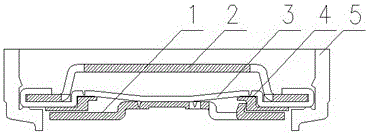
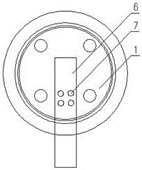
The structure of the cap is as figure 1 As shown, the positive tab 6 needs to be welded on the orifice plate 1 of the cap, and generally 2 to 4 solder spots are welded on the positive tab 6 to ensure the strength of the welding. The general distribution method is as follows figure 2 As shown, the diameter of the solder joint 7 is 0.4 to 1 mm, and the distance between the solder joints is 0.5 to 1 mm. Each solder joint is scattered, and the material of the positive electrode tab 6 and the orifice plate 1 is aluminum. When welding, use a laser The welding machine generates a laser, and the laser melts the positive tab 6 and the orifice plate 1. After cooling, the positive tab 6 and the orifice 1 are connected together. Generally, the width of the positive tab is 2 to 3 mm, so only 2 to 4 welds can be welded. If the tabs are skewed during the welding process, it cannot be guaranteed that all the solder joints are welded on the tabs 6. At the same time, in order to achieve the welding strength, a high-power laser welding machine is required. Insufficient energy may lead to false welding, and excessive energy may cause Explosion or fusion is a process that is not easy to control accurately
Method used
View moreImage
Smart ImageViewing Examples

Examples
Embodiment
[0017] A 18650 battery was fabricated using the invented method, as follows.
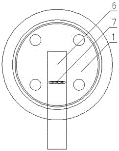
[0018] Use the cap and positive tab that are normally used by the battery. The width of the tab is 2.5 mm. The laser welding power is 100W, and the welding is performed by superimposing 3 solder joints. The superposition distance is that the center distance of the solder joints is equal to half the diameter of the solder joints. The welding strength is tested by tensile force, and the tensile force reaches more than 1200 grams.
Login to View More PUM
 Abstract
The invention relates to a welding method and welding structure of lithium ion battery covers. The welding method comprises a step that a cathode lug is welded on a pore plate of a cover; during welding, a laser-beam welding machine is used for generating a laser light, the laser light melts the cathode lug and the pore plate, and the cathode lug and the pore plate are connected together after being cooled; the welding method is characterized in that two or more solder joints are formed, any two adjacent solder joints partially coincide with each other, and all the solder joints are linearly arrayed; heat generated when the first solder joint is formed by welding can produce a high temperature around solder joints to pre-heat the cathode lug, so that excessive energy is not needed in the area where the second solder joint is formed by welding, the welding is easier, and the subsequent solder joints can utilize the heat generated by the previous soldering joints; the welding machine moves in only one direction. According to the welding method and the welding structure of the lithium ion battery covers, the welding strength of battery covers and lugs is obviously improved, the production difficulty of lithium ion batteries is reduced, and the production efficiency of lithium ion batteries is improved.
Description
technical field [0001] The invention relates to a welding method for a cover or an end cover of a battery, in particular to a welding method and a welding structure for a lithium ion battery cover. Background technique [0002] Lithium-ion batteries were developed and commercialized by Japan's SONY company in the 1990s. Its appearance is a leap in the history of secondary battery development. Lithium-ion batteries have developed rapidly in 3C fields such as mobile phones and notebook computers due to their light weight, high capacity, high working voltage, long service life and no pollution. Its global sales have exceeded the sum of nickel-metal hydride and nickel-cadmium batteries , In recent years, my country's electric vehicles have developed rapidly, and the production and sales have reached the first place in the world. [0003] As the demand for electric vehicles grows, higher requirements are put forward for lithium-ion batteries, which require reliable structure, goo...
Claims
Login to View More Application Information
Patent Timeline
 Patent Type & AuthorityApplications(China)
IPC IPC(8): B23K26/21H01M2/04H01M2/26H01M10/058H01M10/0525B23K101/36
CPCB23K26/21B23K2101/36H01M10/0525H01M10/058H01M50/147H01M50/531Y02E60/10Y02P70/50
Inventor高朋坤陈瑶吴江峰
Owner上海德朗能动力电池有限公司