Machining automatic assembly line for inlet and outlet connecting flange on valve body

An automatic assembly line and connecting flange technology, applied in the direction of manufacturing tools, other manufacturing equipment/tools, etc., can solve the problems of difficult to guarantee shape and position tolerance, difficult control of valve body quality, low processing efficiency, etc., to achieve valve body quality control, The quality of the valve body is easy and the effect of improving the processing efficiency

Inactive Publication Date: 2017-05-31
XUZHOU SHUNFENG VALVE
View PDF7 Cites 4 Cited by
  • Summary
  • Abstract
  • Description
  • Claims
  • Application Information

AI Technical Summary

Problems solved by technology

[0003] In order to solve the problems of the existing ordinary machine tool processing the inlet and outlet connection flanges on the valve body that need to be clamped multiple times, the shape and position tolerance is difficult to guarantee, the quality of the valve body is not easy to control, and the processing efficiency is low, the invention provides a valve body inlet and outlet connection The flange machining automatic assembly line, the valve body inlet and outlet connection flange machining automatic assembly line is controlled by PLC, which can automatically transport, install and process the valve body in order to process the various processing parts of the valve body inlet and outlet connection flanges, ensuring The processing accuracy is improved, the quality of the valve body is easy to control, and the processing efficiency is improved. The present invention is used in conjunction with the valve body mechanical processing automatic assembly line for processing the connecting seat on the valve body, and can complete all the mechanical processing parts on the valve body at one time.

Method used


Image

  • Machining automatic assembly line for inlet and outlet connecting flange on valve body
  • Machining automatic assembly line for inlet and outlet connecting flange on valve body
  • Machining automatic assembly line for inlet and outlet connecting flange on valve body

Examples


Embodiment Construction

[0028] The present invention will be further described below in conjunction with accompanying drawing:

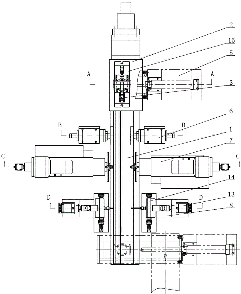
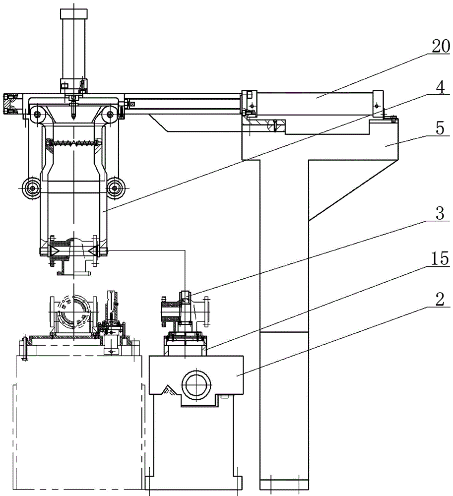
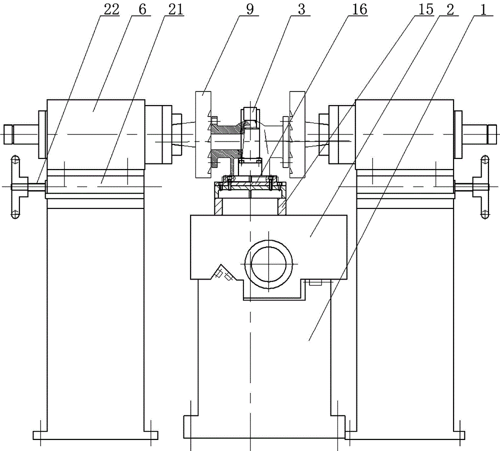
[0029] Depend on Figure 1 to Figure 12As shown, the inlet and outlet of the valve body are connected to the flange machining automatic assembly line, including the bed 1, the numerically controlled sliding table 2 and the pneumatic lift deflection fixture 3, and one side of the numerically controlled sliding table 2 is provided with a pneumatic manipulator 4 and a sliding frame 5. The pneumatic manipulator 4 is installed on the sliding frame 5 and can move up and down and horizontally. The two sides of the bed 1 are successively provided with a symmetrical end face milling power head 6, a symmetrical boring end face power head 7 and a symmetrical drill Hole power head 8, end face milling power head 6 is equipped with milling cutter disc 9 for milling flange end face A, boring end face power head 7 is equipped with boring tool 10 for boring flange sinking end face B; drilli...


PUM


Abstract

The invention relates to a machining automatic assembly line for an inlet and outlet connecting flange on a valve body. The problems that an import and export connecting flange on an existing common machine tool machining valve body needs to be mounted and clamped for multiple times, form and location tolerance is difficult to guarantee, the valve body quality is not easy to control, and the machining efficiency is low are mainly solved. The automatic assembly line is characterized in that symmetrical end face milling power heads (6), symmetrical boring end face power heads (7) and symmetrical drilling power heads (8) are sequentially arranged on the two sides of a tool body (1); and a fixed V-shaped clamping plate (17) and a sliding V-shaped clamping plate (18) are oppositely arranged on a positioning flat plate (16). The machining automatic assembly line can automatically convey and mount and clamp the valve body and machine all the machining parts of the inlet and outlet connection flange on the valve body in sequence, the machining accuracy is guaranteed, the valve body quality is easy to control, the machining efficiency is increased, and all machining parts on the valve body can be completed at one time by the matching use of the automatic assembly line and a valve body machining automatic assembly line for machining a connecting seat on the valve body.

Description

technical field [0001] The invention relates to valve body processing automation equipment, in particular to an automatic assembly line for mechanical processing of valve body inlet and outlet connection flanges. Background technique [0002] The valve body is the main part of the valve. Some large gate valve bodies and globe valve bodies are cast and formed first, and then the valve body blanks are machined to meet the design requirements. The parts on the valve body that need to be machined are as follows: Figure 11 As shown, the valve body is equipped with a connecting seat for installing the valve stem bracket and a connecting flange for the inlet and outlet of the valve body. The parts that need to be processed include the end face of the connecting seat, the counterbore, the annular groove and the bolt connection through hole on the flange of the connecting seat. In addition, it is necessary to machine the flange end face A, the flange sinking end face B and the throu...

Claims


Application Information

Patent Timeline
Patent Type & Authority Applications(China)
IPC IPC(8): B23P23/06
CPCB23P23/06
Inventor 沈永松芦亚萍
Owner XUZHOU SHUNFENG VALVE
Why Eureka
Try Eureka