Method and device for municipal sewage treatment enhancement operation with intermittent aeration of biochemical tank

A technology of urban sewage and operating equipment, applied in the field of water treatment, can solve the problems of easy running of finely crushed sludge flocs, increase of secondary sedimentation load, poor regulation, etc., to reduce sludge treatment output, reduce operating energy consumption, The effect of increasing biomass

Pending Publication Date: 2017-05-31
CHANGCHUN INST OF TECH
View PDF5 Cites 2 Cited by
  • Summary
  • Abstract
  • Description
  • Claims
  • Application Information

AI Technical Summary

Problems solved by technology

[0005] At present, it has been reported that the sewage treatment system load is high and the water effluent effect is poor by increasing the sludge concentration of the biochemical reaction tank.
However, if the concentration of sludge is too high, the concentration of dissolved oxygen in the water will be reduced, and the control is not good. It is easy to turn the aerobic pool into a facultative pool, and the treatment effect will be reduced.
In addition, high sludge concentration is also likely to cause sludge to be easily aged and broken.
Third, the high-concentration sludge from the biochemical tank enters the secondary settling tank, which increases the load of the secondary settling, making its settling performance worse, easy to run fine sludge flocs, and directly affects the effluent effect

Method used


Image

  • Method and device for municipal sewage treatment enhancement operation with intermittent aeration of biochemical tank
  • Method and device for municipal sewage treatment enhancement operation with intermittent aeration of biochemical tank

Examples


Embodiment Construction

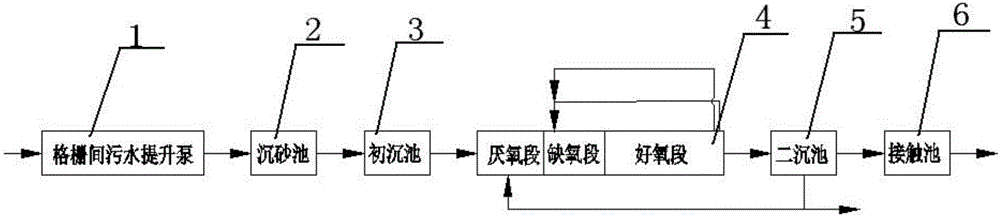
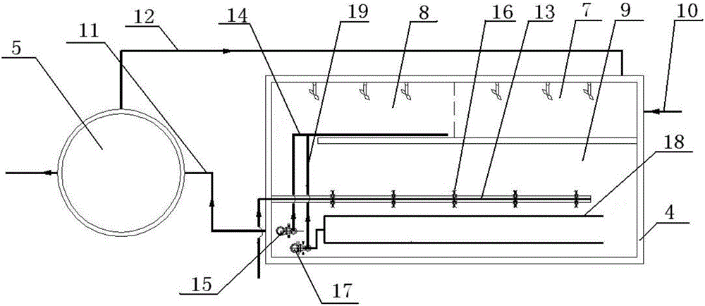
[0020] The device of the present invention adopts grid 1, grit chamber 2, primary sedimentation tank 3, three-stage pond 4, secondary sedimentation pond 5 and contact pond 6, wherein three-stage pond 4 is composed of anaerobic section 7, anoxic section 8, Aerobic section 9, water inlet pipe 10, water outlet pipe 11, sludge return pipe 12, aeration pipe 13, nitrifying liquid return pipe 14 and return pump 15, sludge return pipe 12 is connected between secondary sedimentation tank 5 and anaerobic section 7, the aeration pipe 13 is laid at the bottom of the pool in the aerobic section 9, and the control valve 16 is installed at the standpipe of the aeration pipe 13 at the rear end of the aerobic section 9, and the area at the rear end of the aerobic section 9 forms a sludge sedimentation area , the end of the aerobic section 9 is also equipped with a sludge return pump 17, the inlet of the sludge return pump 17 is connected to a perforated mud collection pipe 18, the perforated mu...


PUM


Abstract

The invention relates to a method and device for municipal sewage treatment enhancement operation with intermittent aeration of a biochemical tank belonging to the technical field of water treatment. The device is constituted by a grid, a sand setting tank, a primary settling tank, a three-zone tank, a secondary settling tank, and a contact tank. The three-zone tank comprises an anaerobic zone, an anoxic zone, an aerobic zone, a sludge return pipe, an aerator pipe, a nitrification liquor return pipe, and a return pump. A control valve is mounted on a riser of the aerator pipe at the rear end of the aerobic zone. A sludge return pump is also mounted at the tail end of the aerobic zone. An inlet of the sludge return pump is connected to a perforated sludge collecting pipe which is mounted at the bottom of the rear end of the aerobic zone, and an outlet of the sludge return pump is connected to an inner return pipe. The other end of the inner return pipe is connected to the nitrification liquor return pipe. When a sewage treatment plant operates under high load, the control valve is closed to stop aeration, and the sludge return pump is started to allow both sludge at the bottom of the settling zone and nitrification liquor to return to the anoxic zone. According to the invention, the municipal sewage is treated by increasing the sludge concentrations of the anoxic zone and the aerobic zone, thereby increasing the biomass of the biochemical tank and reducing the operation energy consumption.

Description

technical field [0001] The invention belongs to the technical field of water treatment, and in particular relates to a method for treating urban sewage and an adopted device. Background technique [0002] According to reports and our unit's long-term monitoring data of sewage treatment plants for many years, during the operation of sewage treatment plants throughout the year, there will be a period of time when the load of organic matter in the influent continues to rise for a long time. When the concentration of organic matter in the sewage entering the sewage treatment plant is too high, exceeding the organic load of the designed biochemical pool, it will bring a heavy treatment burden to the water plant, and at the same time, the water output effect of the water plant will become poor, causing water pollution. [0003] At present, the basis standard for the water quality design of urban sewage treatment plants is the pollutant discharge standard for urban sewage treatment...

Claims


Application Information

Patent Timeline
Patent Type & Authority Applications(China)
IPC IPC(8): C02F9/14C02F3/30
CPCC02F1/52C02F3/301
Inventor 边德军田曦艾胜书任庆凯王帆聂泽兵
Owner CHANGCHUN INST OF TECH
Why Eureka
Try Eureka