High-speed steel convectional cooling annealing pipe

A technology for convective cooling and annealing tubes, which is applied in the direction of furnace types, furnaces, heat treatment furnaces, etc., and can solve the problems of inconvenient sealing of tubes and high cost

Pending Publication Date: 2017-05-31
江苏伟建工具科技有限公司
View PDF0 Cites 4 Cited by
  • Summary
  • Abstract
  • Description
  • Claims
  • Application Information

AI Technical Summary

Problems solved by technology

The current problem with this method of sealing tubes is that the sealed quartz glass tubes are disposable, and the tubes must be broken after the sample is annealed, resulting in high costs, and the sealing of the tubes requires a special vacuum system and Quartz or glass tube heating and softening equipment, it is also very inconvenient to seal the tube

Method used


Image

  • High-speed steel convectional cooling annealing pipe
  • High-speed steel convectional cooling annealing pipe
  • High-speed steel convectional cooling annealing pipe

Examples


Embodiment 1

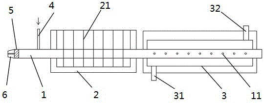
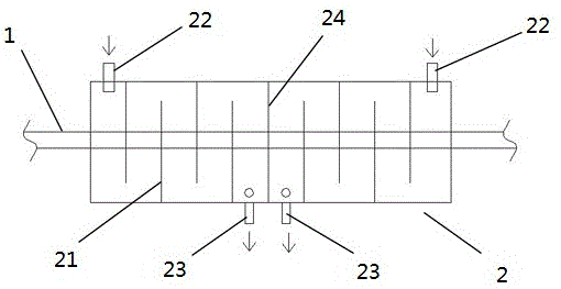
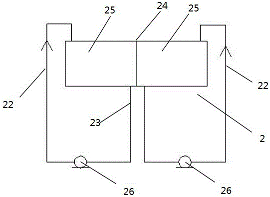
[0024] Embodiment 1: A high-speed steel convective cooling annealing tube, the high-speed steel convective cooling annealing tube includes an annealing tube main body; the annealing tube main body is sequentially provided with a combustion chamber and a water bath along the high-speed steel movement direction; the water bath There is a baffle in the center of the water bath to divide the water bath into two sub-water baths that are not connected to each other; each end of the water bath is provided with an inlet pipe; A water outlet pipe; each of the sub-water baths is provided with a circulating water pump, and a relatively flowing cooling water flow is formed in the water bath through the circulating water pump; the water in the water bath flows over the annealing tube body;; the annealing tube body The pipe section arranged in the combustion chamber is provided with a plurality of gas holes on both sides in the horizontal direction; the combustion chamber is provided with an ...

Embodiment 2

[0026] Embodiment 2: A high-speed steel convective cooling annealing tube, the high-speed steel convective cooling annealing tube includes an annealing tube body; the annealing tube body is sequentially provided with a combustion chamber and a water bath along the high-speed steel movement direction; the water bath There is a baffle in the center of the water bath to divide the water bath into two sub-water baths that are not connected to each other; each end of the water bath is provided with an inlet pipe; A water outlet pipe; each of the sub-water baths is provided with a circulating water pump, and a relatively flowing cooling water flow is formed in the water bath through the circulating water pump; the water in the water bath flows over the annealing tube body;; the annealing tube body The pipe section arranged in the combustion chamber is provided with a plurality of gas holes on both sides in the horizontal direction; the combustion chamber is provided with an igniter; t...

Embodiment 3

[0028] Embodiment 3: A high-speed steel convective cooling annealing tube, the high-speed steel convective cooling annealing tube includes an annealing tube main body; the annealing tube main body is sequentially provided with a combustion chamber and a water bath along the moving direction of the high-speed steel; the water bath There is a baffle in the center of the water bath to divide the water bath into two sub-water baths that are not connected to each other; each end of the water bath is provided with an inlet pipe; A water outlet pipe; each of the sub-water baths is provided with a circulating water pump, and a relatively flowing cooling water flow is formed in the water bath through the circulating water pump; the water in the water bath flows over the annealing tube body;; the annealing tube body The pipe section arranged in the combustion chamber is provided with a plurality of gas holes on both sides in the horizontal direction; the combustion chamber is provided wit...


PUM

PropertyMeasurementUnit
Apertureaaaaaaaaaa
Lengthaaaaaaaaaa

Abstract

The invention discloses a high-speed steel convectional cooling annealing pipe. The high-speed steel convectional cooling annealing pipe is characterized in that the high-speed steel convectional cooling annealing pipe comprises an annealing pipe body; a combustion chamber and a water bath trough are sequentially arranged on the annealing body in the high-speed steel movement direction; a baffle is arranged in the center of the water bath trough and divides the water bath trough into two sub water bath troughs which do not communicate with each other; the two ends of the water bath trough are each provided with a water inlet pipe; the ends, close to the baffle, of the sub water bath troughs are each provided with a water outlet pipe; each sub water bath trough is provided with a circulating pump, and relatively flowing cooling water flow is formed in the water bath trough through the circulating pumps; water in the water bath trough spills over the annealing pipe body; a plurality of gas holes are formed in the two side faces, in the horizontal direction, of a pipe section, arranged in the combustion chamber, of the annealing pipe body; a fresh air inlet is formed in the lower end face of the combustion chamber; a smoke outlet is formed in the upper end face of the combustion chamber; a flexible sealing block is arranged at the high-speed steel outlet end of the annealing pipe body; and a hydrogen inlet is formed in position, at one side of the water bath trough, of the annealing pipe body.

Description

Technical field [0001] The invention relates to the field of metal annealing, in particular to an annealing tube for high-speed steel. Background technique [0002] Annealing is a metal heat treatment process, which refers to slowly heating the metal to a certain temperature, keeping it for a sufficient time, and then cooling it at an appropriate speed. The purpose is to reduce the hardness, improve the machinability; eliminate residual stress, stabilize the size, reduce deformation and crack tendency; refine the crystal grain, adjust the structure, and eliminate the structure defect. To be precise, annealing is a heat treatment process for materials, including metallic materials and non-metallic materials. Moreover, the annealing purpose of new materials is similar to that of traditional metal annealing. [0003] Annealing is a very commonly used experimental method for sample preparation and sample processing in scientific research and production. For some samples that can be a...

Claims


Application Information

Patent Timeline
IPC IPC(8): C21D1/26C21D6/00C21D9/52
CPCC21D1/26C21D6/00C21D9/525
Inventor 王卫和
Owner 江苏伟建工具科技有限公司
Why Eureka
Try Eureka