Hold hoop type automatic leveling and anchoring device for replacement of steel pipe concrete arch bridge suspenders and suspender replacing method thereof

A technology of concrete filled steel tube and anchoring device, which is applied to arch bridges, bridge reinforcement, bridge forms, etc., can solve the problems of large structure size, complex construction procedures, and high manufacturing costs, and achieves fewer machined components, which is convenient for standardized construction and manufacturing costs. low effect

Active Publication Date: 2017-05-31
LIUZHOU OVM ENG +1
View PDF8 Cites 1 Cited by
  • Summary
  • Abstract
  • Description
  • Claims
  • Application Information

AI Technical Summary

Problems solved by technology

[0002] At present, most of the suspension rod replacement devices of steel pipe concrete arch bridges are mainly temporary suspension rods or temporary hoisting devices. The upper part of the arch needs to be welded to fix the leveling wedge or anti-slip stop to achieve the leveling of the arch and facilitate the installation of beams. Or the purpose of anti-slip; when the temporary suspender or the temporary hoisting device needs to be transferred to the next suspender replacement place, the beam on the arch needs to be hoisted by large-scale lifting equipment. The disadvantages are: the engineering work is intensive and the welding quality is difficult to control , it is easy to damage the original steel pipe concrete arch rib and coating, the wedge block cannot be used repeatedly, the progress of demolition and restoration work is slow, the consumption of large lifting equipment is large, and the construction cost is high
[0003] The application publication number is: CN102926332 A, and the title of the invention is "tool hanger device and replacement method for steel arch bridge hanger replacement", which discloses a tool hanger device for steel arch bridge hanger replacement, and its disadvantages are still It is necessary to weld the limit device near the position of the suspender at each place. It is difficult to control the welding quality on site, and it will damage the arch rib and coating of the original steel structure. The material of the limit device cannot be used for turnover. The welding position is repaired; the number of steel wire ropes around the arch circle is large, the construction process is complicated, the engineering work inten

Method used


Image

  • Hold hoop type automatic leveling and anchoring device for replacement of steel pipe concrete arch bridge suspenders and suspender replacing method thereof
  • Hold hoop type automatic leveling and anchoring device for replacement of steel pipe concrete arch bridge suspenders and suspender replacing method thereof
  • Hold hoop type automatic leveling and anchoring device for replacement of steel pipe concrete arch bridge suspenders and suspender replacing method thereof

Examples


Embodiment 1

[0058] A hoop type automatic leveling and anchoring device for the replacement of the suspender of the steel tube concrete arch bridge:

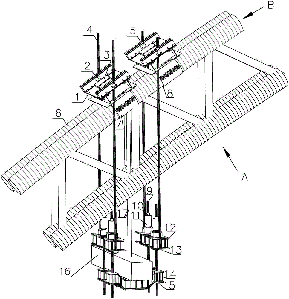
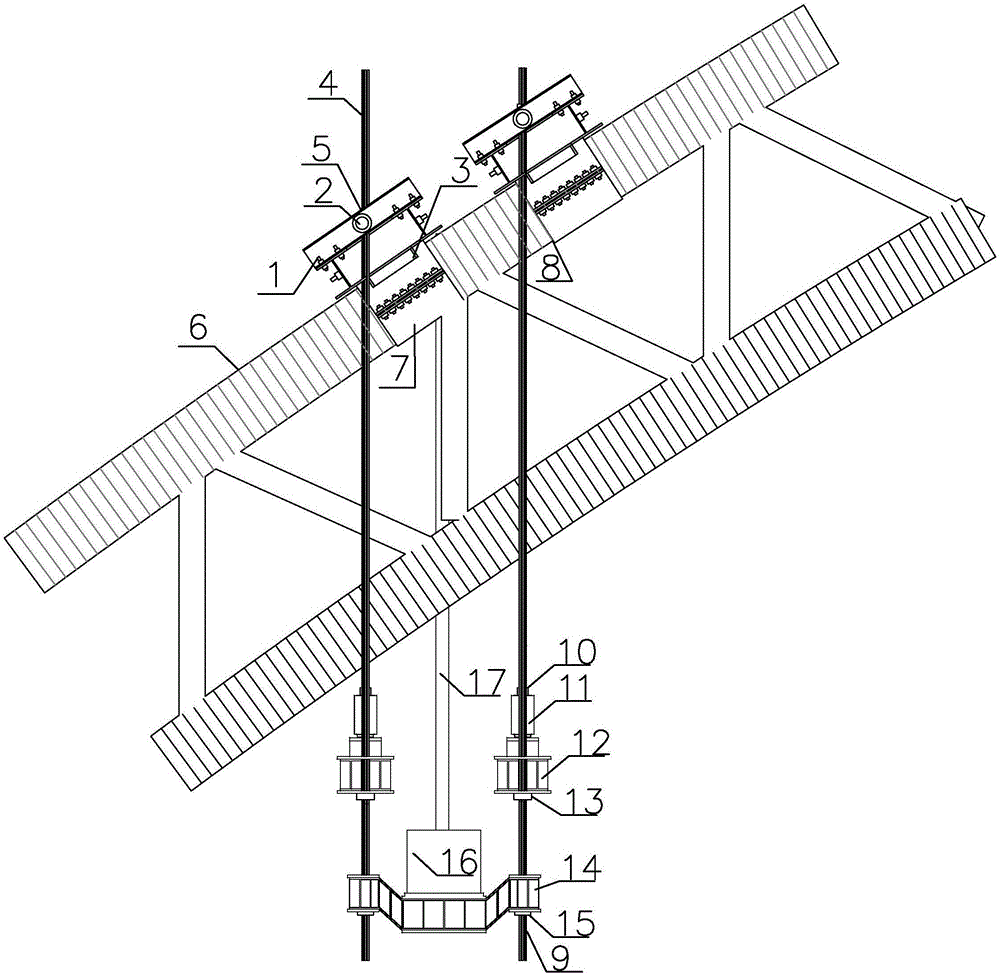
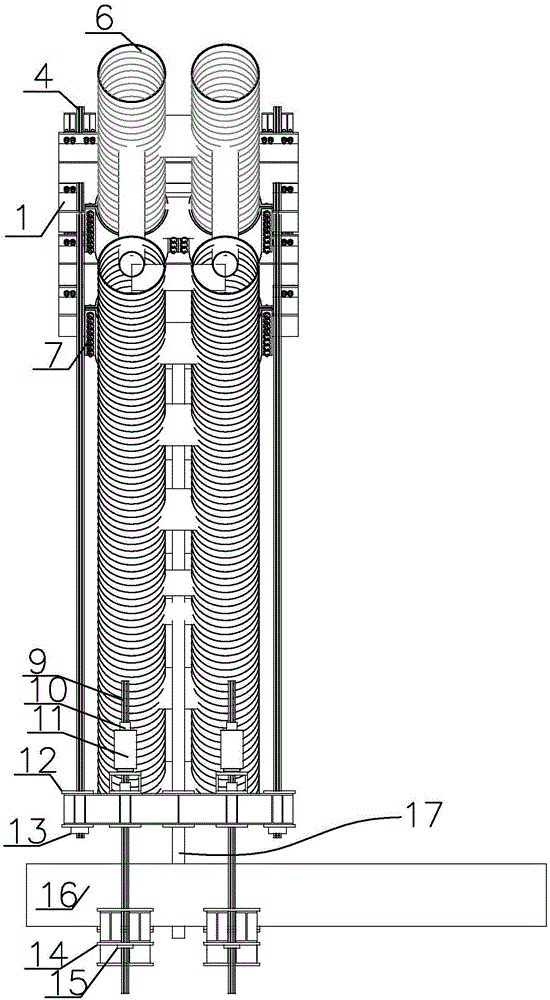
[0059] Such as figure 1 As shown, the hoop type automatic leveling anchor device includes: upper beam 1, tension end anchor I5, upper temporary cable 4, tension end anchor II10, conversion beam 12, fixed end anchor I13, lower temporary cable 9. The lower joist 14, fixed end anchor Ⅱ15 and two hoop-type arch anchorage anti-skid systems installed on the arch of the steel tube concrete arch bridge. Tool 2, anti-skid steel box 3, upper beam 1, anti-skid hoop 7 and rubber pad 8 (see Figure 1-Figure 6 );

[0060] The two sides of the anti-skid steel box 3 are rectangular steel plates, the other two sides are saddle-shaped steel plates, and the top surface is a rectangular steel plate, which is tailor-welded into a steel box structure (see Figure 7 , Figure 8 );

[0061] The upper beam 1 is a two-layer structure, and the two are connected b...

Embodiment 2

[0067] A method for replacing the suspension rod of a steel pipe arch bridge, which is a method for replacing the suspension rod of a steel pipe arch bridge by adopting the hoop type automatic leveling and anchoring device described in Embodiment 1 for replacing the suspension rod of a steel pipe arch bridge, and comprising the following steps:

[0068] A. Install the hoop type automatic leveling anchor device for the replacement of the suspender of the steel tube concrete arch bridge:

[0069] Such as figure 1 , figure 2 , image 3 , Figure 4 , Figure 5 , Figure 6 As shown, the hoop-type automatic leveling anchorage device used for replacing the suspender of the steel tube concrete arch bridge has upper beam 1, tension end anchor I5, upper temporary cable 4, tension end anchor II10, conversion beam 12, and fixed end Anchor Ⅰ13, lower temporary cable 9, lower joist 14, fixed end anchor Ⅱ15, and two hoop arch anchorage anti-skid systems installed on the arch bridge arc...


PUM


Abstract

A hold hoop type automatic leveling and anchoring device for replacement of steel pipe concrete arch bridge suspenders comprises upper cross beams, tensioning-end anchorage devices I and II, upper and lower temporary ropes, transfer beams, fixed-end anchorage devices I and II,lower supporting beams and two hold hoop type arch apex anchoring and anti-slip systems installed on a steel pipe concrete arch bridge arch, wherein each hold hoop type arch apex anchoring and anti-slip system consists of two rotary lifting appliances, an anti-slip steel box, an upper cross beam, an anti-slip hold hoop and a rubber pad. In a working state, the upper and lower temporary ropes respectively penetrate through the upper cross beam or the lower transfer beam and a jack and are anchored by using the tensioning-end anchorage devices I and II and the fixed-end anchorage devices I and II, and the lower supporting beams support the lower surfaces of suspender cross beams. The rubber pads are arranged between the anti-slip hold hoops and the side faces of the steel pipe arch, the lower-portion cambered surfaces of the anti-slip steel boxes are fixedly connected with the anti-slip hold hoops, one side of each upper-layer #-shaped structure of the upper cross beams tightly attaches to the side face of the corresponding anti-slip steel box, and the other side of each structure is in bolted connection with the corresponding anti-slip steel box through high-strength screws. The hold hoop type automatic leveling and anchoring device is simple in structure, smaller in size, simple and convenient to construct and high in work efficiency.

Description

technical field [0001] The invention relates to a bridge construction machine tool, in particular to a tool hanger device for replacing the hanger of a steel pipe truss concrete arch bridge and a method for replacing the hanger of the arch bridge. Background technique [0002] At present, most of the suspension rod replacement devices of steel pipe concrete arch bridges are mainly temporary suspension rods or temporary hoisting devices. The upper part of the arch needs to be welded to fix the leveling wedge or anti-slip stop to achieve the leveling of the arch and facilitate the installation of beams. Or the purpose of anti-slip; when the temporary suspender or the temporary hoisting device needs to be transferred to the next suspender replacement place, the beam on the arch needs to be hoisted by large-scale lifting equipment. The disadvantages are: the engineering work is intensive and the welding quality is difficult to control , It is easy to damage the original steel pi...

Claims


Application Information

Patent Timeline
IPC IPC(8): E01D22/00E01D4/00
CPCE01D4/00E01D22/00
Inventor 窦勇芝韦福堂甘科李东平孙长军汪孝龙黎祖金
Owner LIUZHOU OVM ENG
Why Eureka
Try Eureka