Servo fast forging valve and servo valve system

A servo valve and servo motor technology, applied in servo motor components, multi-port valves, valve devices, etc., can solve problems such as servo quick forging valve string oil, etc., and achieve the effect of smooth opening curve, fast switching speed and high frequency

Active Publication Date: 2019-04-26
青岛海德马克智能装备有限公司
View PDF7 Cites 0 Cited by
  • Summary
  • Abstract
  • Description
  • Claims
  • Application Information

AI Technical Summary

Problems solved by technology

[0004] The first purpose of the present invention is to provide a servo fast forging valve to solve the phenomenon of oil leakage in the existing servo fast forging valve

Method used


Image

  • Servo fast forging valve and servo valve system
  • Servo fast forging valve and servo valve system
  • Servo fast forging valve and servo valve system

Examples


Embodiment 1

[0037]The specific implementation of this embodiment is as follows:

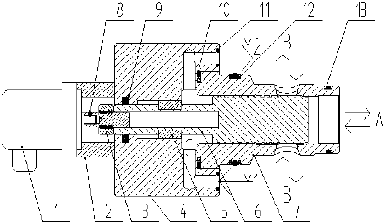
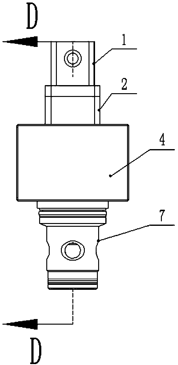
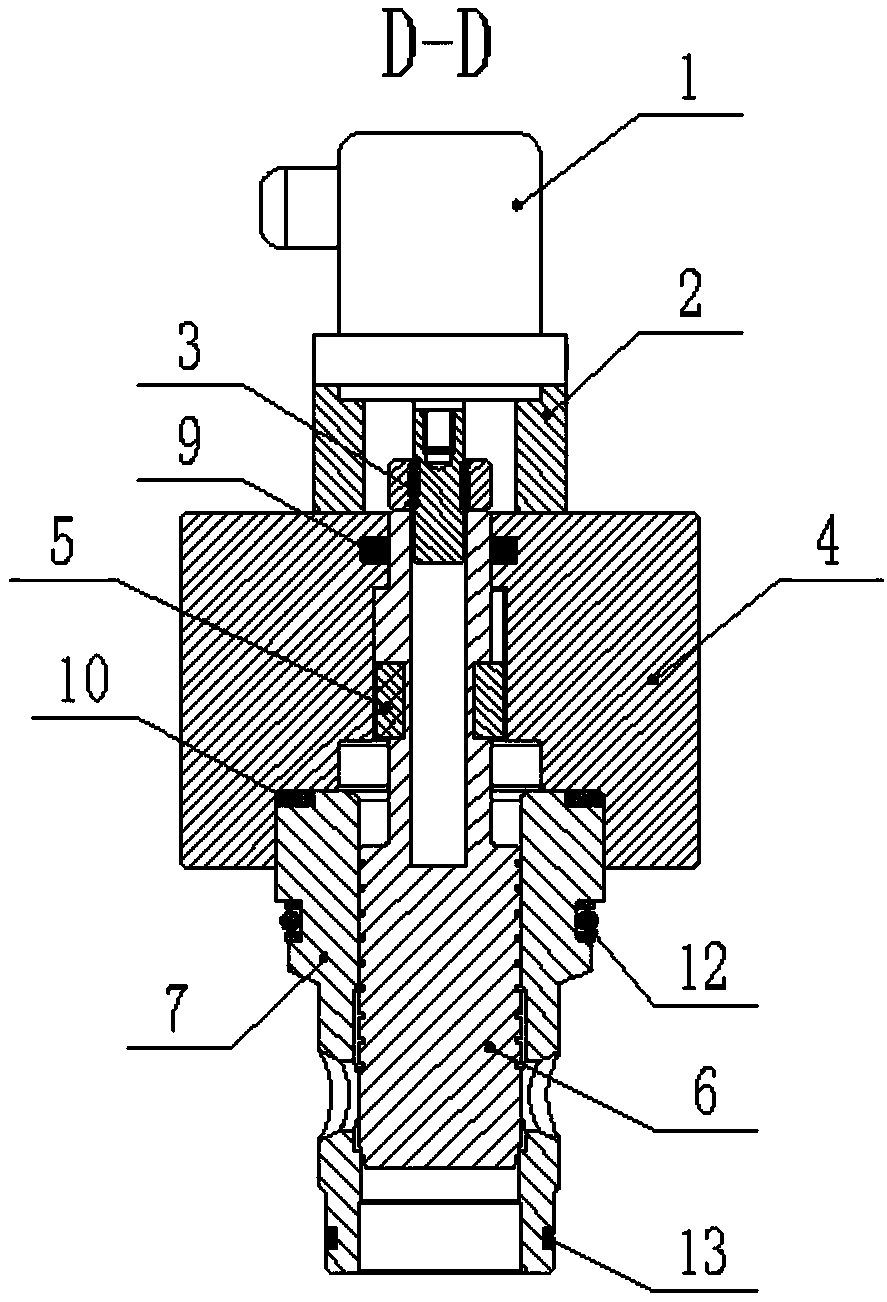
[0038] Such as figure 1 As shown in -4, a servo fast forging valve provided by this embodiment includes a servo motor 1, a bracket 2, a guide lubricating cover plate 4 and a valve sleeve 7 arranged in sequence from left to right, the bracket 2, and a guide lubricating cover plate 4 A ball screw assembly 3 is installed through the center of the valve sleeve 7, the output shaft of the servo motor 1 is threadedly connected with the lead screw of the ball screw assembly 3, and the guide lubricating cover plate 4 is tightly matched with the end face of the valve sleeve 7. connected as one structure;

[0039] The valve sleeve 7 is provided with a servo valve core 6, and the servo valve core 6 is connected with the bearing bolts of the ball screw assembly 3 as an integral structure;

[0040] The leading screw can drive the bearing of the ball screw assembly 3 to move up and down to regulate the opening and closin...

Embodiment 2

[0053] A servo valve system provided in this embodiment includes the above-mentioned servo quick forging valve, and also includes a programmable logic controller;

[0054] When there is high-pressure oil in chamber A, the programmable logic controller sends an instruction to make the servo motor 1 rotate clockwise according to the preset sinusoidal curve, so that the valve core moves upward and the chamber A communicates with chamber B, and the hydraulic oil flows from A Cavity flows to Cavity B;

[0055] When there is high-pressure oil in chamber B, the programmable logic controller sends an instruction to make servo motor 1 rotate clockwise according to the sinusoidal curve set in advance, so that the valve core moves upward, and chamber B communicates with chamber A, and the hydraulic oil flows from Chamber B flows through chamber A.

[0056] Such as figure 1 As shown in -4, the servo fast forging valve includes a servo motor 1, a bracket 2, a guide lubricating cover 4 an...


PUM


Abstract

The invention provides a servo quick forging valve and a servo valve system and relates to the field of quick forging hydraulic machines, in particular to the servo quick forging valve. The servo quick forging valve comprises a servo motor, a support, a guiding lubricating cover plate and a valve sleeve which are sequentially arranged from left to right, a ball screw assembly is installed in the centers of the support, the guiding lubricating cover plate and the valve sleeve in a penetrating mode, and an output shaft of the servo motor is connected with a lead screw of the ball screw assembly in a threaded mode; the guiding lubricating cover plate and the end face of the valve sleeve are tightly matched in a sealed mode and connected into an integrated structure, a servo valve core is installed in the valve sleeve, and the servo valve core and a bearing bolt of the ball screw assembly are connected to into an integrated structure; and a bearing of the ball screw assembly can be driven by the lead screw to vertically move to adjust opening and closing of a valve. The invention further relates to the servo valve system. The servo valve system comprises the servo quick forging valve and a programmable logic controller. Through the technical scheme of the servo quick forging valve and the servo valve system, the oil swapping phenomenon occurring in an existing servo quick forging valve is avoided.

Description

technical field [0001] The invention relates to the technical field of rapid forging hydraulic presses, in particular to a servo rapid forging valve and a servo valve system. Background technique [0002] Electric-pneumatic proportional valves and servo valves can be divided into pressure type and flow type according to their functions. The pressure-type proportional / servo valve converts the input electrical signal linearly into gas pressure; the flow-type proportional / servo valve converts the input electrical signal into gas flow. Due to the compressibility of gas, the movement speed of actuators such as cylinders or air motors does not only depend on the gas flow. Also depends on the load size of the actuator. Precise control of gas flow is therefore often not necessary. Simple pressure or flow proportional / servo valves are rarely used, and the combination of pressure and flow is often more widely used. Electric-pneumatic proportional valves and servo valves are mainly...

Claims


Application Information

Patent Timeline
Patent Type & Authority Patents(China)
IPC IPC(8): F15B13/02F16K11/044F16K31/04F16K27/02B21J9/12
CPCB21J9/12F15B13/02F16K11/044F16K27/0263F16K31/047
Inventor 王安基
Owner 青岛海德马克智能装备有限公司
Why Eureka
Try Eureka