Eureka AIR delivers breakthrough ideas for toughest innovation challenges, trusted by R&D personnel around the world.

Large-capacity garbage high-temperature gasification spraying combustion system

A large-capacity, garbage-based technology, applied in the field of waste energy release and utilization systems, can solve problems such as polluting and poisoning the environment, energy waste, and harmful gas dioxin emissions that cannot be eliminated

Active Publication Date: 2017-05-31
刘振亮
View PDF5 Cites 1 Cited by
  • Summary
  • Abstract
  • Description
  • Claims
  • Application Information

AI Technical Summary

Problems solved by technology

Since the combustion process of garbage on the grate starts from the bottom layer, it enters five stages of drying, volatile analysis, volatile matter combustion, coke combustion and slag burnout, and the separated volatile matter is directly discharged into the waste gas after the volatile matter is burned. To the boiler heat exchanger, it is discharged after heat exchange. During this process, the flue gas contains unburned volatiles, dioxins and other components. Unburned volatiles cause energy waste, and dioxins cause environmental pollution. Therefore, the defect of the working principle of waste incineration power generation in the prior art has caused major technical problems, the emission of harmful gases, especially dioxins, cannot be eliminated, the energy loss is serious, and the environment is polluted and poisoned

Method used


Image

  • Large-capacity garbage high-temperature gasification spraying combustion system
  • Large-capacity garbage high-temperature gasification spraying combustion system
  • Large-capacity garbage high-temperature gasification spraying combustion system

Examples


Embodiment Construction

[0023] Below in conjunction with accompanying drawing and embodiment, further elaborate the present invention. In the following detailed description, certain exemplary embodiments of the invention are described by way of illustration only. Needless to say, those skilled in the art would realize that the described embodiments can be modified in various different ways, all without departing from the spirit and scope of the present invention. Accordingly, the drawings and description are illustrative in nature and not intended to limit the scope of the claims.

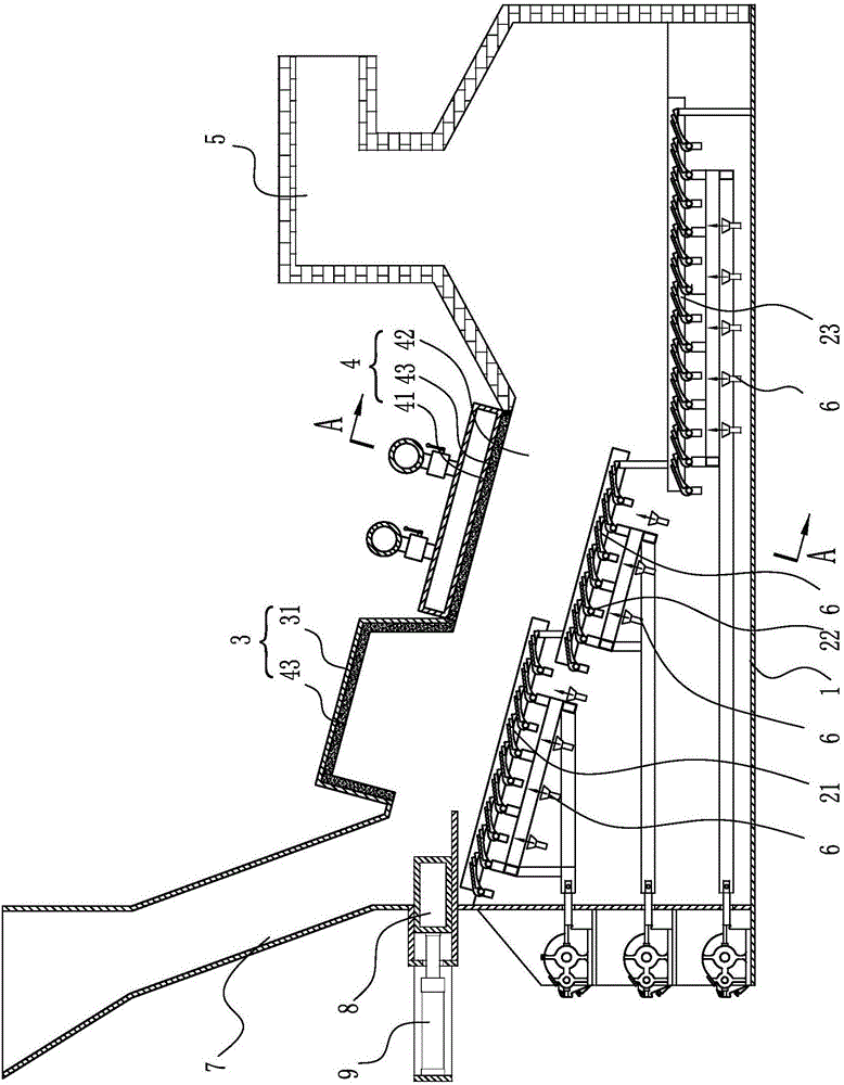
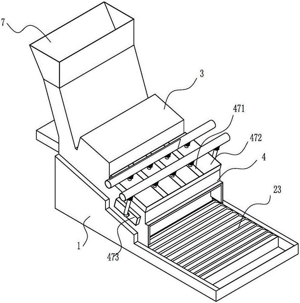
[0024] The large-capacity waste high-temperature gasification and combustion system includes a furnace body base 1, and the furnace body base 1 is provided with a drying section reciprocating grate 21, a combustion section reciprocating grate 22, and a slag section in sequence from high to low. The reciprocating grate 23, the reciprocating grate 21 of the drying section, the reciprocating grate 22 of the injection combus...


PUM


Abstract

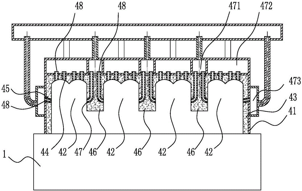
The invention discloses a large-capacity garbage high-temperature gasification spraying combustion system comprising a furnace body base. A drying section furnace body and a spraying combustion section furnace body are arranged on the furnace body base. The spraying combustion section furnace body comprises a spraying combustion main furnace body. A spraying combustion rotational flow hearth is arranged in the spraying combustion main furnace body. Spraying combustion top spraying openings embedded in a fireproof material layer are formed in the top wall of the spraying combustion rotational flow hearth, and spraying combustion outer side spraying openings embedded in the fireproof material layer are formed in the side wall of the spraying combustion rotational flow hearth. The spraying combustion top spraying openings and the spraying combustion outer side spraying openings are formed in the spraying combustion rotational flow hearth, so that two combustion vortexes are formed in the spraying combustion rotational flow hearth, particles and components which are incomplete in gasification combustion are mixed and combusted fully, the temperature of the combustion vortexes can reach 1200-1300 DEG C, dioxin is also decomposed completely at the stage, and combustion is more fierce; and the large-capacity garbage high-temperature gasification spraying combustion system is a breakthrough technological progress of the garbage incineration technology and has great economic benefits and social benefits.

Description

technical field [0001] The invention relates to the technical field of energy utilization, in particular to a waste energy release utilization system that injects heat energy after gasification and combustion to a heat energy collection and utilization system. Background technique [0002] Municipal solid waste incineration power generation has the three advantages of harmlessness, resource utilization and reduction, which plays a major role in improving urban sanitation and environment. It is an optimal way to deal with municipal solid waste today and has become the best way to deal with urban solid waste in my country. One of the main methods. At present, the thermal efficiency of most waste incineration power generation boilers in China is low, which directly affects the economic benefits of waste incineration power plants. The stable combustion control and adjustment of waste incineration power generation boilers are the key points and difficulties in operation. Engineer...

Claims


Application Information

Patent Timeline
Patent Type & Authority Applications(China)
IPC IPC(8): F23G5/00F23G5/04F23G5/027F23G5/44
CPCF23G5/002F23G5/0276F23G5/04F23G5/44F23G5/444F23G2203/101F23G2203/105F23G2205/10F23G2201/40F23G2201/10F23G2202/10Y02E20/12
Inventor 刘国田代吉发张大鹏冯言超
Owner 刘振亮
Why Eureka
Eureka Blog
Learn More