Aluminum melting furnace capable of performing low-oxygen high-temperature combustion through flue gas reflowing

A high-temperature combustion and aluminum melting furnace technology, which is applied to gas fuel burners, burners, combustion methods, etc., can solve the problems of uneven mixing of gas and air, inability to effectively control the combustion state, incomplete combustion, etc., and achieve improved combustion and heat transfer process, save the initial investment cost, and reduce the effect of usage

Active Publication Date: 2017-05-31
郑州釜鼎热能技术有限公司
View PDF6 Cites 1 Cited by
  • Summary
  • Abstract
  • Description
  • Claims
  • Application Information

AI Technical Summary

Problems solved by technology

Looking at the current structure of aluminum melting (smelting) furnaces and the various combustion devices and systems used, many of them have various problems in structure and performance caused by design concept problems, which will inevitably cause a gap between gas and air. Inhomogeneous mixing and incomplete combustion, and the inability to effectively control its combustion state
In particular, the combustion and heat transfer process in the aluminum melting (smelting) furnace has not been well ...

Method used


Image

  • Aluminum melting furnace capable of performing low-oxygen high-temperature combustion through flue gas reflowing
  • Aluminum melting furnace capable of performing low-oxygen high-temperature combustion through flue gas reflowing

Examples


Embodiment Construction

[0008] The specific implementation manners of the present invention will be described in detail below in conjunction with the accompanying drawings.

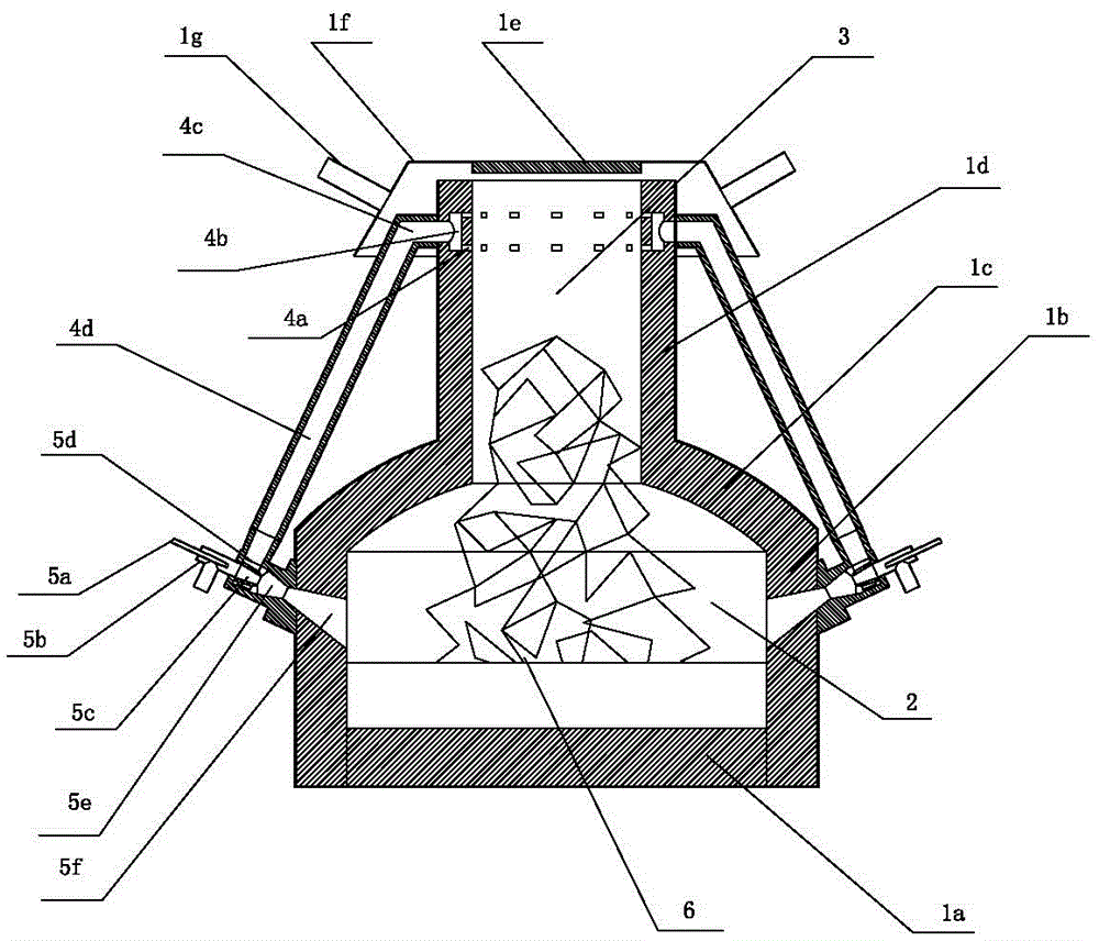
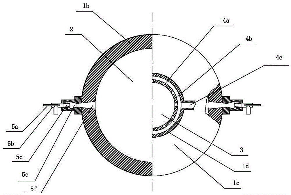
[0009] Such as figure 1 and figure 2 As shown, the structure of the present invention is that the periphery of the circular furnace bottom 1a is surrounded by an annular furnace wall 1b upwards, and the top of the annular furnace wall is covered with an upper arc-shaped top cover 1c, and the middle part of the upper arc-shaped top cover has a through hole. The through hole of the arc-shaped top cover is equipped with a middle feeding channel wall 1d upwards. The space surrounded by the middle feeding channel wall is the feeding and smoke outflow channel 3, and the space surrounded by the annular furnace wall is the combustion and smelting furnace 2, charging and smoke The gas outlet channel 3 communicates downwards with the through hole and the combustion and smelting furnace. The top of the feeding and flue gas outlet channel...


PUM


Abstract

The invention relates to an aluminum melting furnace capable of performing low-oxygen high-temperature combustion through flue gas reflowing, and aims to effectively realize temperature control, decrease the content of nitrogen oxide and save energy in the melting process of the aluminum melting furnace. The aluminum melting furnace is characterized in that the top of an annular furnace wall surrounding the bottom of the furnace is provided with an annular arc-shaped top cover; a middle charging channel wall body is formed in a through hole in the middle part of the top cover; a charging and flue gas discharging channel is formed inside the middle charging channel wall body; a combustion melting hearth is formed in the annular furnace wall; the middle part of an exhaust hood on the top of the charging and flue gas discharging channel is provided with a furnace top cover; the periphery of the exhaust hood is provided with an exhaust hood outlet pipe; a combustor is arranged in the circumferential direction of the annular furnace wall; a flue gas outlet on the inner wall of the charging channel wall body is connected with the charging and flue gas discharging channel; the outer end of the flue gas outlet is connected with an inner ring of a flue gas converging annular channel; a flue gas converging main pipe communicating with an outer ring of the annular channel is connected with a flue gas reflow inlet through a flue gas reflow communication pipe; the annular furnace wall is provided with an operation furnace door and a molten liquid discharging hole. By adopting the aluminum melting furnace, control of the combustion temperature is realized, the combustion temperature is lowered, control of the content of the nitrogen oxide is realized, and the using amount of coal gas is reduced.

Description

technical field [0001] The invention relates to heat utilization equipment for smelting furnaces in industrial kilns, and is an aluminum melting (smelting) furnace which utilizes flue gas backflow, low oxygen, and high temperature combustion, and is especially suitable for burning high calorific value gas fuels. Background technique [0002] At present, in order to meet the requirements of energy saving and environmental protection, industrial furnaces and kilns obtain efficient and controllable complete combustion under the conditions of burning different gases in the combustion devices of heat utilization equipment, and effectively reduce nitrogen oxides (NO X ) and sulfide (SO X ) has become the main technical direction to finally achieve the goals of high efficiency, energy saving, environmental protection and safe use. For this reason, in the structural design of industrial furnaces and their combustion devices, in addition to achieving rapid and uniform mixing and sta...

Claims


Application Information

Patent Timeline
IPC IPC(8): F27B14/14F27D17/00F23D14/02F23D14/66
CPCF23D14/02F23D14/66F27B14/14F27B2014/146F27D17/004Y02E20/34
Inventor 陈维汉陈云鹤杨海涛张佳鹏
Owner 郑州釜鼎热能技术有限公司
Why Eureka
Try Eureka