A positive and negative time-point flow device for a tube-fin radiator

A radiator and tube-fin type technology, applied in the direction of indirect heat exchangers, heat exchanger shells, tubular elements, etc., can solve the problems of limited effect, restricted fixed structure, etc., to increase surface area, improve heat exchange efficiency, and improve unit The effect of physical performance

Inactive Publication Date: 2019-01-29
HUAZHONG UNIV OF SCI & TECH
View PDF7 Cites 0 Cited by
  • Summary
  • Abstract
  • Description
  • Claims
  • Application Information

AI Technical Summary

Problems solved by technology

In current product design, the heat pipes of tube-fin radiators are usually flat tubes. However, with the continuous improvement of vehicle design requirements, its application is usually limited by the fixed structure, and the effect is limited.

Method used


Image

  • A positive and negative time-point flow device for a tube-fin radiator
  • A positive and negative time-point flow device for a tube-fin radiator
  • A positive and negative time-point flow device for a tube-fin radiator

Examples


specific Embodiment

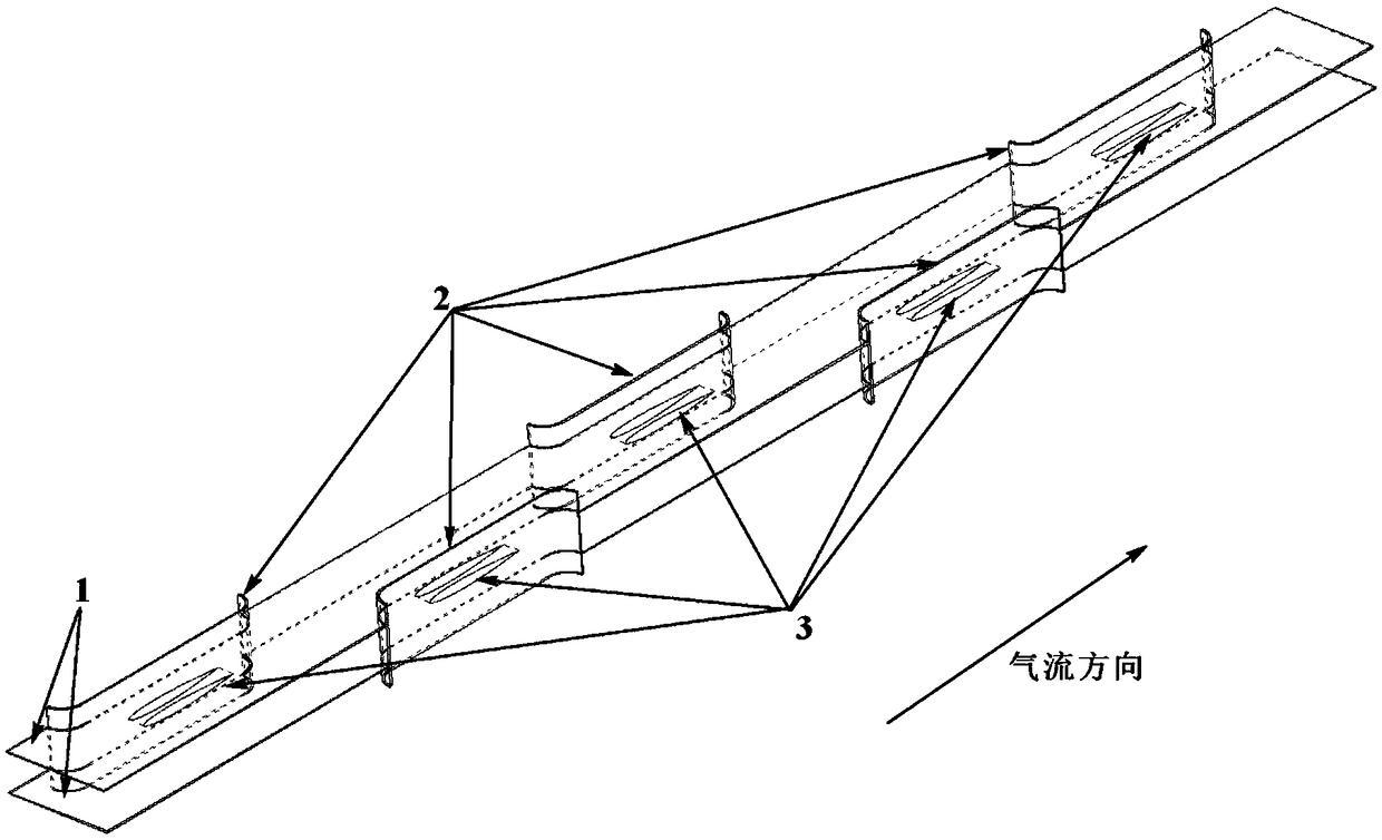
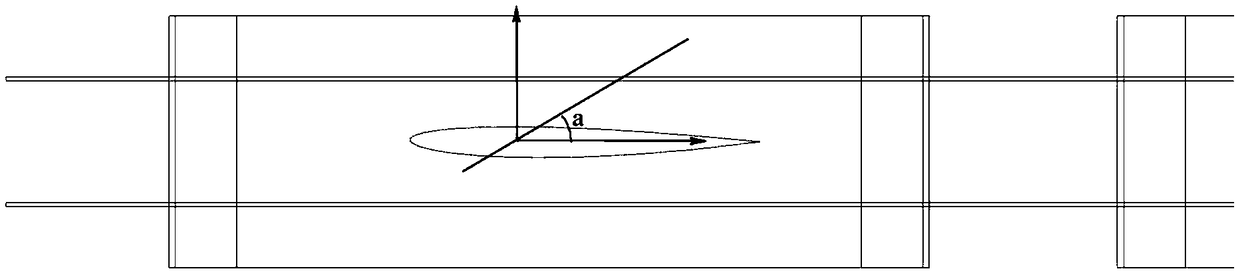
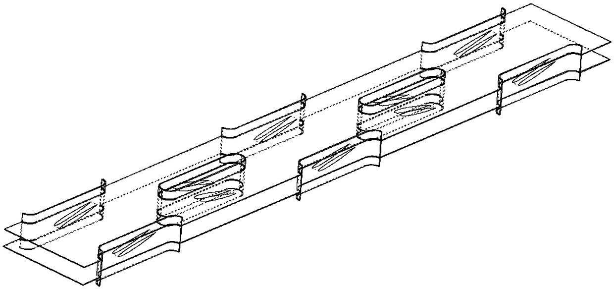
[0039] The heat pipe 2 stands on the ground or on a fixed stand; punch holes on the fin 1 according to the corresponding position of the heat pipe 2, and remove the punched material; after the hole position of the fin 1 is aligned with the heat pipe 2, insert the heat pipe 2, After inserting, they are arranged in specific positions from bottom to top; the outer geometric features of the guide rudder 3 are processed into a symmetrical aircraft airfoil. If the guide rudder has a relatively large thickness, the external geometric features are maintained. Fixed on both sides of the heat pipe 2, if the thickness is small, then retain the surface geometric features, do not close the side of the non-fixed end; fin 1 and guide rudder 3 are installed crosswise in an alternate order; after the installation is completed, the fin 1, heat pipe 2 and The steering rudder 3 is integrally brazed to ensure structural strength.


PUM


Abstract

The invention belongs to the field of heat radiating devices / equipment and particularly discloses a clockwise and counterclockwise convection device of a tube and fin type heat radiator. The clockwise and counterclockwise convection device comprises fins, heat tubes and guide rudders; a plurality of forming holes are punched in the parallel fins according to the positions and structures of the heat tubes; the heat tubes are sleeved into the forming holes so as to be fixed; two side walls of the heat tubes are symmetrically and fixedly provided with the guide rudders which are shaped like low-resistance aircraft wings and are mounted according to a certain angle, and the mounting angles of the guide rudders on symmetric positions are same; air among the fins forms two parallel air screws with completely opposite rotating directions in the vertical direction; and tangent parts of the two screws realize air convection. By using the clockwise and counterclockwise convection device disclosed by the invention, the heat exchange effect among the heat tubes, the wall surfaces of the fins and the air are enhanced on the basis that the normal flow of the air is guaranteed, meanwhile, the rotation of air in runners is realized by virtue of the mounting angle, and the performance of the heat radiator is enabled to be capable of adapting to the change of various working conditions through the clockwise and counterclockwise rotation of the air in the two adjacent runners.

Description

technical field [0001] The invention belongs to the field of radiator equipment, and more specifically relates to a forward and reverse time-point flow device of a tube-fin radiator, which can improve the working performance of the radiator of an engine cooling system in a power cabin of an engineering vehicle. Background technique [0002] Because diesel engine has a series of advantages such as low speed, high torque and high power, it is widely used as a power source in engineering vehicles. Since diesel is used as its main energy source, the heat brought by fuel combustion needs to be dissipated to the environment in time. The role of the engine cooling system is to ensure that the cylinder temperature of the diesel engine remains within a reasonable range. If the cylinder temperature is too high, the oil film seal will be damaged, and even "burning cylinder" will occur; if the cylinder temperature is too low, there will be The combustion efficiency is low, and the fuel...

Claims


Application Information

Patent Timeline
Patent Type & Authority Patents(China)
IPC IPC(8): F28F1/02F28D15/02F28F3/00F28F9/24
CPCF28D15/0233F28F1/02F28F3/00F28F9/24
Inventor 蒋炎坤刘佳鑫何书默
Owner HUAZHONG UNIV OF SCI & TECH
Why Eureka
Try Eureka