Temperature measuring control device and method for novel battery and assembled battery

A technology for control devices and battery packs, applied to measuring devices, thermometers with physical/chemical changes, thermometers, etc., can solve problems such as battery short-circuit fire, detection line damage, safety accidents, etc., and achieve easy operation and temperature measurement accuracy High and wide detection range effect

Inactive Publication Date: 2017-05-31
SHANGHAI CHANGYUAN WAYON CIRCUIT PROTECTION CO LTD
View PDF3 Cites 5 Cited by
  • Summary
  • Abstract
  • Description
  • Claims
  • Application Information

AI Technical Summary

Problems solved by technology

[0008] (d) Since they use metal conductive materials, metal wires are susceptible to corrosion, causing measurement failures;
[0009] (e) Due to too many wires, it is not conducive to the heat dissipation of the measured object body;
[0010] (f) Since they are made of plastic materials (polyolefin, nylon, polyurethane, rubber) on the outside, they cannot be detected when they encounter electrolyte corrosion, which may easily cause a short circuit between them and the battery and cause a fire;
[0011] (g) Because they are easy to be broken down under high voltage conditions, they will cause damage to the detection line and cause safety accidents

Method used


Image

  • Temperature measuring control device and method for novel battery and assembled battery
  • Temperature measuring control device and method for novel battery and assembled battery
  • Temperature measuring control device and method for novel battery and assembled battery

Examples


Embodiment Construction

[0107] In order to make the objectives, technical solutions, and advantages of the present invention clearer, the embodiments of the present invention will be described in detail below with reference to the accompanying drawings. It should be noted that the described embodiments are only intended to facilitate the understanding of the present invention, but not Play any limiting role.

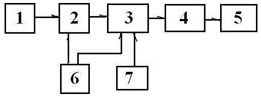
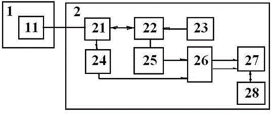
[0108] See figure 1 Schematic diagram of the structure of the present invention, figure 2 It is a schematic diagram of the structure of the temperature signal acquisition module of the present invention, Figure 16 It is a schematic diagram of the installation of the temperature sensing front end of the present invention, Figure 8 It is a schematic diagram of the structure of the independent power supply module of the present invention, Picture 9 It is a schematic diagram of the structure of the battery management module of the present invention, Figure 14 Schematic diagram of the structure of ...


PUM


Abstract

The invention discloses a temperature measuring control device and method for a novel battery and an assembled battery, which are applied to static and dynamic temperature measurement of various batteries and battery packs thereof. The temperature measuring control device comprises a temperature sensing front end, a temperature signal acquisition and calculation module, a battery management module, a communication module and a terminal and independent display module, and is powered by a battery pack, wherein the temperature sensing front end, the temperature signal acquisition and calculation module, the battery management module, the communication module and the terminal and independent display module are sequentially connected; an independent power supply module is connected with the temperature signal acquisition and calculation module and the battery management module respectively; the battery pack is connected with the battery management module; the temperature sensing front end comprises a fiber or grating sensor, and is arranged on the battery pack through a heat-conducting and fixing component. The temperature measuring control device is convenient to arrange, easy and convenient to operate and high in temperature measuring accuracy, can effectively monitor the temperature change of each battery in each region in real time, is continuous in detection point, wide in range, electrically neutral, resistant to radio frequency and electromagnetic interference, flame-proof, explosion-proof, resistant to corrosion and resistant to high pressure, and can work in a variety of environments.

Description

Technical field [0001] The invention relates to a temperature measurement control device and method for a novel battery and an assembled battery, and belongs to the field of battery safety protection. Background technique [0002] With the continuous application of power batteries and assembled batteries in daily work and life, the application environment is constantly changing, and batteries and assembled batteries need a safer temperature control system. [0003] With the continuous development of new energy, the number of batteries and assembled batteries continues to increase, and the working temperature detection points also continue to increase. Conventional temperature measurement methods are no longer suitable, such as thermistors, thermocouples and other temperature sensing front ends. Each battery is A temperature sensing front end is needed. 300 batteries require 300 temperature sensing front ends, and 600 wires are required to connect to the temperature sensing front en...

Claims


Application Information

Patent Timeline
IPC IPC(8): G01K11/32G01K11/3206
CPCG01K11/32
Inventor 毛卫清
Owner SHANGHAI CHANGYUAN WAYON CIRCUIT PROTECTION CO LTD
Why Eureka
Try Eureka