A secondary electronic measuring device
A technology of secondary electrons and measuring devices, applied in measuring devices, material analysis using wave/particle radiation, instruments, etc., can solve the difficulties of receiving reverse electrons, measuring the degree of neutralization of implanted ions, complex and expensive equipment, etc. problems, to avoid surface damage, to achieve the total current measurement, the effect of bombardment damage is small
- Summary
- Abstract
- Description
- Claims
- Application Information
AI Technical Summary
Problems solved by technology
Method used
Image
Examples
Embodiment 1
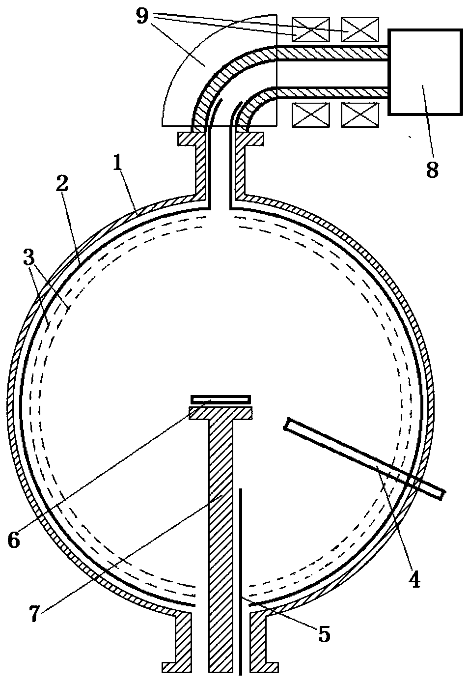
[0027] Such as figure 1 The secondary electron measurement device shown is composed of a vacuum chamber 1, a receiving electrode 2, a grid 3, a plasma torch 4, a plasma excitation electrode 5, a sample to be tested 6, a sample carrier 7, an electron gun 8, and an electron deflection transmission system 9 And other systems such as vacuum, power supply, and measurement.
[0028] The sample carrying bracket 7 is set in the vacuum chamber 1, the sample 6 to be tested is set on the sample carrying bracket 7, and the primary electrons are emitted by the electron gun 8 into the vacuum chamber 1 and bombard the sample 6 to be tested, which can be loaded with high-pressure plasma The excitation electrode 5 and the plasma torch 4 can be set separately or at the same time. After completing the secondary electron measurement of one or several electron pulses of the sample 6 to be tested, close the vacuum pump valve of the electron gun and the vacuum chamber, and pass the The plasma gener...
Embodiment 2
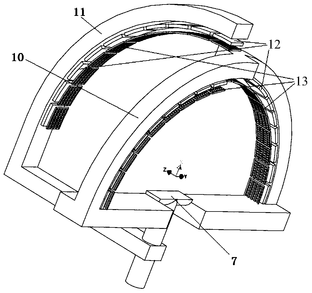
[0036] figure 2 Shown is the secondary electron current angular distribution measurement bracket diagram. When measuring the angular distribution of the secondary electron current, the figure 1 The receiving electrode 2, the grid 3 and the electron deflection transmission system 9 in the measuring device are removed, the electron gun can directly shoot into the sample to be tested, and the sample carrying bracket 7 is changed to figure 2 Structure.
[0037] figure 2 Among them, the Y-axis turret 10 can independently rotate along the Y-axis parallel to the surface of the sample to be measured relative to the sample-carrying bracket 7; X-axis rotation; the sample carrying bracket 7 , the Y-axis turntable 10 and the X-axis turntable 11 can rotate together along the Z-axis parallel to the surface of the sample to be measured and perpendicular to the Y-axis. On the inside of the Y-axis turret 10 and the X-axis turret 11 relative to the sample, a mutually insulated secondary ...
PUM
 Abstract
Description
Claims
Application Information
 - R&D
- Intellectual Property
- Life Sciences
- Materials
- Tech Scout
- Unparalleled Data Quality
- Higher Quality Content
- 60% Fewer Hallucinations
Browse by: Latest US Patents, China's latest patents, Technical Efficacy Thesaurus, Application Domain, Technology Topic, Popular Technical Reports.
© 2025 PatSnap. All rights reserved.Legal|Privacy policy|Modern Slavery Act Transparency Statement|Sitemap|About US| Contact US: help@patsnap.com


