Method for preparing needle point of atomic force microscope

An atomic force microscope and needle tip technology, applied in scanning probe microscopy, scanning probe technology, measuring devices, etc., can solve the problems of easy loss, delay of experiment progress, interruption of experiment process, etc., so as to speed up the experiment process and improve sharpness degree, method, effective effect

Active Publication Date: 2017-05-31
JINHUA VOCATIONAL TECH COLLEGE
View PDF9 Cites 4 Cited by
  • Summary
  • Abstract
  • Description
  • Claims
  • Application Information

AI Technical Summary

Problems solved by technology

When the probe tip of the traditional atomic force microscope is worn, its radius of curvature will become larger, and the image resolution of the scanned sample will be reduced. Therefore, the imaging of the atomic force microscope is greatly affected by its probe, so the tip of the atomic force microscope is a consumable , in the process of use, especially after high-precision experiments, it is very easy to wear and tear. It is time-consuming and laborious to replace the needle tip, and it will delay the progress of the experiment. At present, the methods for growing thorns on the tip of the silicon needle tip include: ion or electron beam deposition, focused ion beam etching , chemical vapor deposition of carbon nanotubes or metal nanotubes, etc.
However, the defects of these methods are as follows: first, the cost is high; second, it needs to be carried out in a vacuum chamber and has high requirements for vacuum; third, it cannot be carried out in situ, and the experimental process needs to be interrupted, making it impossible to replace the new needle tip in a convenient and timely manner. , to delay the progress of the experiment, the method for preparing the tip of the atomic force microscope can solve this problem

Method used


Image

  • Method for preparing needle point of atomic force microscope
  • Method for preparing needle point of atomic force microscope
  • Method for preparing needle point of atomic force microscope

Examples


Embodiment Construction

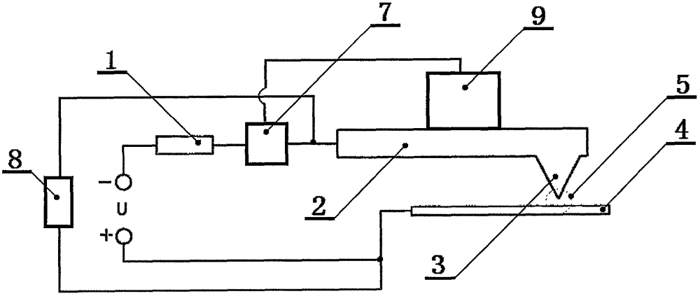
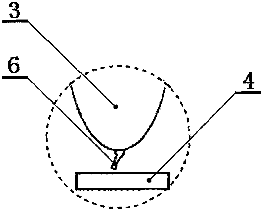
[0025] Such as figure 1It is a schematic diagram of the present invention, and the device for realizing the method mainly includes a resistor 1, a cantilever 2, a needle tip 3, a sample 4, a gap between the sample and the needle tip 5, a thorn 6, a current feedback system 7, a photoelectric feedback system 8, Piezoelectric driver 9, power supply U, wherein the positive pole of the power supply U is connected to the sample 4, the negative pole is connected to the resistor 1 in turn, the current feedback system 7, the cantilever 2 and the needle point 3, the needle point 3 is fixed below the cantilever 2, and the sample 4 includes The first specific sample and the second specific sample are located below the needle point 3; with the power supply U, the resistor 1, the current feedback system 7, the cantilever 2, the needle point 3, the gap between the sample and the needle point 5 and the sample 4 composed of a current feedback loop, when the current feedback system 7 is in the ...


PUM


Abstract

The invention relates to the field of atomic force microscopes, and provides a method for preparing a needle point of the atomic force microscope. A current feedback loop is composed of a power supply U, a resistor, a current feedback system, a cantilever, a needle point, a gap between the needle point and a sample, and the sample; concave pits with the diameter of 100nm and the depth of 30nm are formed in the surface of a first specific sample every 100nm; bulges with the height of 20nm and the diameter of 10nm are formed on the surface of a second specific sample every 20nm; a needle-shaped object is generated by the first specific sample, and a needle-shaped object, which is vertical to the surface of the sample, grows by utilizing the second specific sample; a parameter for determining whether the needle point is sharp or not is checked: the other sample with a relatively flat surface is used and works at a phase shaft mode; an initial amplitude is set to be AO, a scanning distance is set to be 15nm and a pre-set value is 0.6AO; if the phase shift on the flat surface is negative, the needle point is a sharp needle point capable of meeting experiment requirements; if the phase shift is not negative, a process of applying the power supply to form a high electric field in the gap between the needle point and the sample is repeated.

Description

technical field [0001] The invention relates to the field of preparation of a nanostructured atomic force microscope tip, in particular to a simple and effective method for preparing an atomic force microscope tip that can directly prepare a tip that meets the experimental requirements on the original tip under normal temperature and atmospheric conditions. Background technique [0002] Atomic Force Microscope (AFM) is an instrument that uses the interaction force between atoms and molecules to observe the microscopic topography of the object surface. The basic principle is: by fixing a nanoscale probe on a sensitively manipulated On the micron-scale elastic cantilever, when the needle tip is very close to the sample, the force between the atoms at the tip of the needle tip and the surface atoms of the sample will cause the micron-scale elastic cantilever to bend and deviate from its original position; at the same time, a beam of laser light hits the cantilever and reflected...

Claims


Application Information

Patent Timeline
Patent Type & Authority Applications(China)
IPC IPC(8): G01Q60/38
CPCG01Q60/38
Inventor 赵永建方晓华张向平
Owner JINHUA VOCATIONAL TECH COLLEGE
Why Eureka
Try Eureka