
A carbon emission quantification method for machine tool equipment products based on embodied carbon energy

A carbon emission and carbon emission technology, applied in the direction of instruments, ICT adaptation, data processing applications, etc., can solve the problems of inconsistent boundaries, difficult quantitative carbon emission calculation, etc., to achieve a unified calculation process, and ensure practicability and consistency. , avoid the effect of complexity

Active Publication Date: 2019-02-05
XI AN JIAOTONG UNIV
View PDF3 Cites 0 Cited by
  • Summary
  • Abstract
  • Description
  • Claims
  • Application Information

AI Technical Summary

Problems solved by technology

[0003] The current product carbon emission method focuses on the carbon emission modeling, analysis and calculation of the entire system, and does not pay attention to the carbon emission analysis that focuses on the product itself, resulting in subsequent low-carbon optimization and improvement that targets products and the current carbon emission quantification method The boundary is not uniform; carbon emissions are multi-source and dynamic, accompanied by the tight coupling of material flow and energy flow, it is difficult to quantitatively calculate carbon emissions within the boundaries of the entire system

Method used


Image

  • A carbon emission quantification method for machine tool equipment products based on embodied carbon energy
  • A carbon emission quantification method for machine tool equipment products based on embodied carbon energy
  • A carbon emission quantification method for machine tool equipment products based on embodied carbon energy

Examples


Embodiment Construction

[0053] The present invention will be further described in detail below in conjunction with the accompanying drawings.

[0054] 4.1 Analysis of material flow and energy flow of machine tool equipment products

[0055] 4.1.1 Carbon emission source analysis

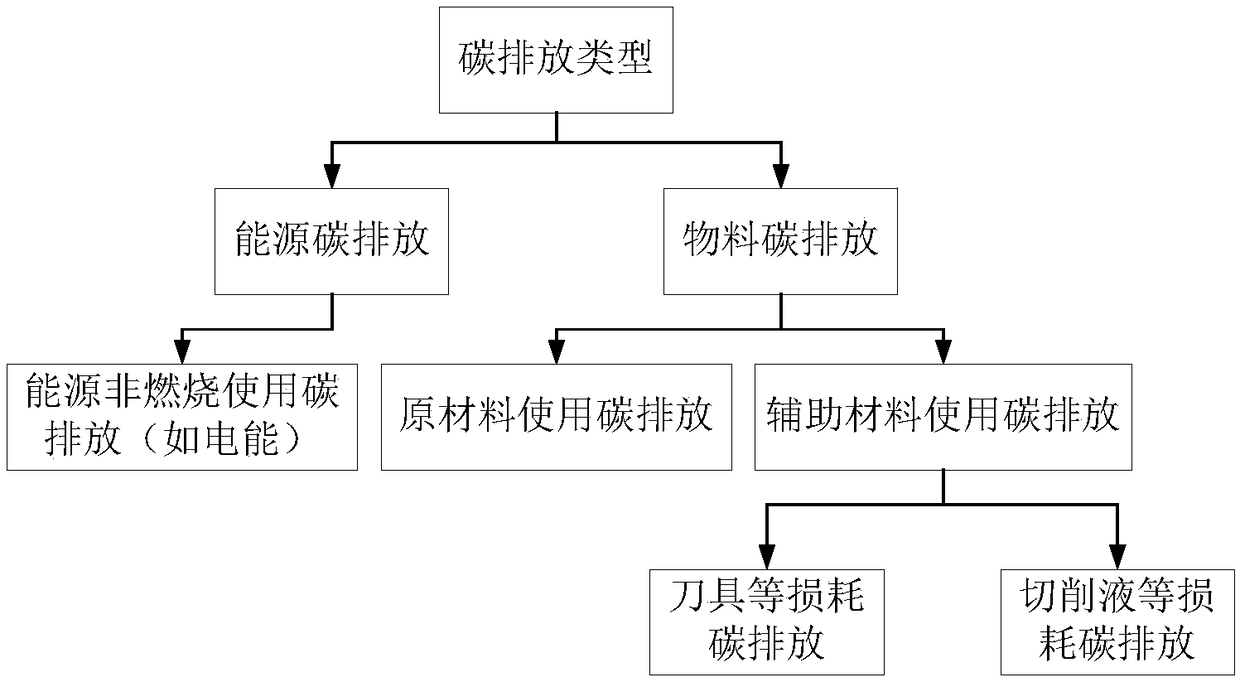
[0056] refer to figure 1 , to quantify carbon emissions, it is first necessary to delineate and classify the carbon emission sources of machine tool equipment products in the life cycle, which are divided into energy carbon and material carbon. Material carbon includes the carbon emissions generated by the raw material acquisition process of each part of machine tool equipment products, and the carbon emissions generated by tool loss and cutting fluid loss of machine tool equipment products.

[0057] 4.1.2 Determination of material flow and energy flow

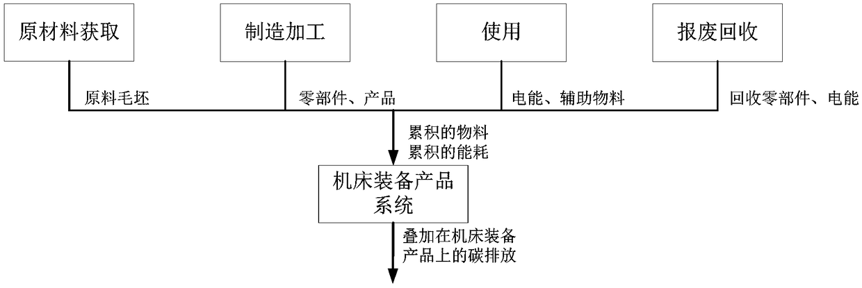
[0058] Further, the material flow and energy flow of machine tool equipment products are analyzed, and the material flow is expressed as the change of materials. In the ...


PUM

PropertyMeasurementUnit
densityaaaaaaaaaa

Abstract

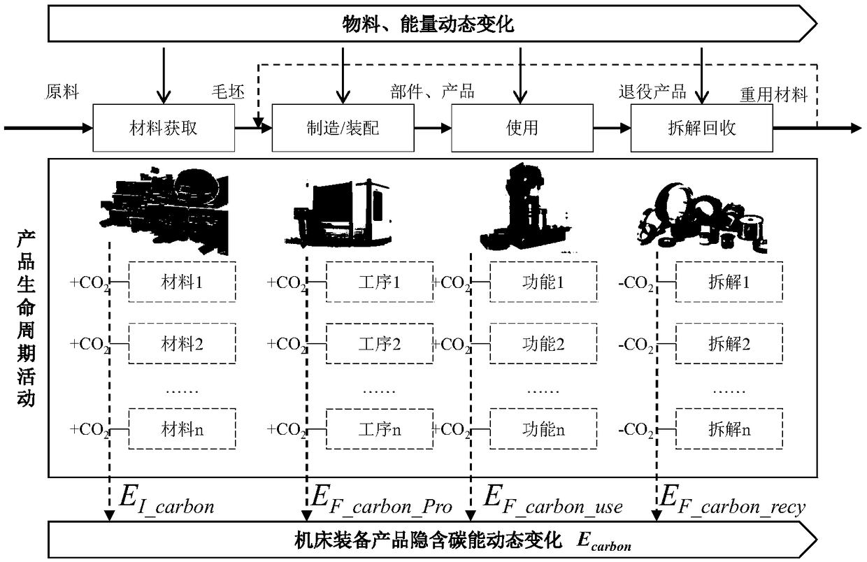
The invention provides an embodied carbon energy-based machine tool equipment product carbon emission quantification method. The method comprises three parts, i.e., machine tool equipment product material flow and energy flow analysis, a machine tool equipment product carbon emission quantification model and an embodied carbon energy-based carbon emission quantification method. A machine tool equipment product material flow and energy flow superposition principle is provided by analyzing the characteristics of energy flow and material flow; a carbon emission boundary model at a main lifecycle stage is established, and a machine tool equipment product carbon emission quantification principle is given based on an embodied carbon energy concept; an embodied carbon energy-based specific carbon emission calculation formula is obtained according to the characteristics of the main lifecycle stage. The invention adopts an embodied carbon energy quantification method, which takes a product as the boundary, for providing data support for a low carbon design, and is more close to the target object requirements of actual low-carbon optimization improvement, so that the practicality and consistency of the carbon emission boundary and a calculation result are guaranteed, and an effective basis and theoretical support are provided for energy conservation and emission reduction of products manufactured by machine tool equipment.

Description

Technical field: [0001] The invention belongs to the technical field of advanced manufacturing and automation, and in particular relates to a method for quantifying carbon emissions of machine tool equipment products based on hidden carbon energy. Background technique: [0002] Since the beginning of the 21st century, with the rapid development of the human economy, energy consumption has increased year by year, and the ensuing environmental problems have become more prominent. A global environmental problem - the greenhouse effect caused by greenhouse gases has seriously restricted human survival and social development. At the same time, my country's manufacturing industry presents the characteristics of "three highs and one low" of "high investment, high energy consumption, high pollution, and low efficiency", which has seriously restricted my country's strategic deployment to become a world manufacturing power. As a typical representative of the manufacturing industry, t...

Claims


Application Information

Patent Timeline
Patent Type & Authority Patents(China)
IPC IPC(8): G06Q10/06G06Q50/26
CPCG06F2219/10G16Z99/00Y02A90/10Y02P90/82Y02P90/84
Inventor 周光辉鲁麒周策常丰田田长乐
Owner XI AN JIAOTONG UNIV
Learn More