
A Reflective X-ray Source Structure of Patterned Carbon Nanotube Cathode

A carbon nanotube cathode, carbon nanotube technology, which is applied in the directions of X-ray tube electrodes, X-ray tube parts, etc., can solve the problems of miniaturization of unfavorable ray sources, short service life, slow start-up speed, etc., and achieves compact structure. , the effect of high emission current density and low threshold voltage

Active Publication Date: 2019-05-17
SHENZHEN INST OF ADVANCED TECH CHINESE ACAD OF SCI
View PDF4 Cites 0 Cited by
  • Summary
  • Abstract
  • Description
  • Claims
  • Application Information

AI Technical Summary

Problems solved by technology

[0004] The technical problem to be solved by the present invention is to provide a reflective X-ray source structure with a patterned carbon nanotube cathode, which can solve the problem of high operating temperature, high power consumption, and low start-up speed caused by the use of hot cathodes as electron sources in traditional X-ray sources. Slow, short service life, not conducive to the miniaturization of the ray source, and at the same time realize the regulation of field emission

Method used


Image

  • A Reflective X-ray Source Structure of Patterned Carbon Nanotube Cathode
  • A Reflective X-ray Source Structure of Patterned Carbon Nanotube Cathode
  • A Reflective X-ray Source Structure of Patterned Carbon Nanotube Cathode

Examples


Embodiment Construction

[0021] The following will clearly and completely describe the technical solutions in the embodiments of the present invention with reference to the accompanying drawings in the embodiments of the present invention. Obviously, the described embodiments are only some, not all, embodiments of the present invention. Based on the embodiments of the present invention, all other embodiments obtained by persons of ordinary skill in the art without creative efforts fall within the protection scope of the present invention.

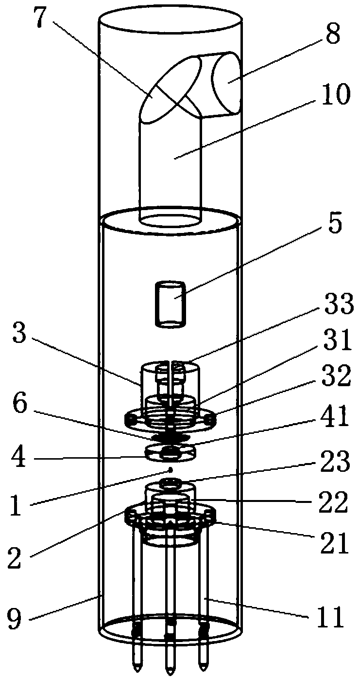
[0022] like figure 1 As shown, a preferred embodiment of the present invention, a patterned carbon nanotube transmission X-ray source structure, which includes a carbon nanotube 1, a conductive base 2, an insulating cover 3, an insulating spacer 4, a focusing barrel 5, and a grid 6 , an anode target 7, a beryllium window 8 and a ball tube 9, the carbon nanotube 1, a conductive base 2, an insulating cover 3, an insulating gasket 4, a focusing barrel 5 and a grid 6 a...


PUM


Abstract

The invention provides a reflective X-ray source structure of a patterned carbon nanotube cathode. The reflective X-ray source structure comprises a carbon nanotube, a conductive base, an insulation cover, an insulation gasket, a focus barrel, a grid mesh, an anode target, a berylium window and a sphere tube. The bottom of the insulation cover matches the conductive base. The carbon nanotube, the insulation gasket and the grid mesh are mounted on the top of the conductive base in sequence from bottom to top. The focus barrel is arranged on the top of the insulation cover. After voltages are applied on the conductive base and the grid mesh until a threshold value arrives, the intensity of a current generated by the carbon nanotube is controlled through the grid mesh; electrons are pulled out from the end face of the carbon nanotube; the electrons are focused through the focus barrel, light spots are formed and hit the anode target; and X rays are generated and are transmitted towards the berylium window. Through adoption of the reflective X-ray source structure, the problem that the working temperature is high, the power consumption is high, the starting speed is slow, the service life is short and a ray source is not easy to realize due to the fact that a thermionic cathode is taken as an electron source of a traditional X-ray source can be solved, and moreover, field emission is controlled.

Description

technical field [0001] The invention relates to an X-ray source structure, in particular to a reflective X-ray source structure of a patterned carbon nanotube cathode. Background technique [0002] Computed tomography equipment (computed tomography, CT) is a powerful medical imaging diagnostic equipment, which uses X-rays to scan a certain range of the human body layer by layer to obtain projection information, and then performs data processing and image reconstruction in the computer. The traditional spiral CT imaging system mainly includes X-ray source, high voltage generator, detector, frame, slip ring and other components. [0003] As one of the key core components of the CT system, the X-ray source determines the imaging mode and imaging performance of the CT system to a certain extent. The traditional X-ray source consists of a hot cathode and an anode. When working, electron beams are generated by thermally exciting free electrons. Then, under the action of the anode...

Claims


Application Information

Patent Timeline
Patent Type & Authority Patents(China)
IPC IPC(8): H01J35/06H01J35/04
CPCH01J35/04H01J35/06
Inventor 冯鸿涛张志诚陈艳谢耀钦
Owner SHENZHEN INST OF ADVANCED TECH CHINESE ACAD OF SCI
Learn More