Positive electrode and secondary battery

A positive electrode sheet and positive electrode film technology, which is applied in the field of positive electrode sheets and secondary batteries, can solve the problems of loss of positive electrode active material ratio, reduction of positive electrode active material content, and energy density reduction, so as to enhance electronic conductivity and adhesion , enhanced electronic conductivity, and improved safety performance

Active Publication Date: 2019-06-11
NINGDE AMPEREX TECH
View PDF4 Cites 0 Cited by
  • Summary
  • Abstract
  • Description
  • Claims
  • Application Information

AI Technical Summary

Problems solved by technology

Increasing the amount of conductive agent can improve the electronic conductivity of the positive electrode, but it will lose the ratio of the positive active material, so that the content of the positive active material is relatively reduced, resulting in a decrease in energy density, and the increase of the conductive agent generally consumes less There is too much binder, which leads to the disadvantage of insufficient adhesion; although increasing the amount of binder can improve the adhesion of the positive electrode layer to a certain extent, it will increase the impedance of the battery and deteriorate the kinetic performance. A series of problems such as the reduction of effective active substance content, and the improvement of adhesion is very limited

Method used


Image

  • Positive electrode and secondary battery
  • Positive electrode and secondary battery
  • Positive electrode and secondary battery

Examples


preparation example Construction

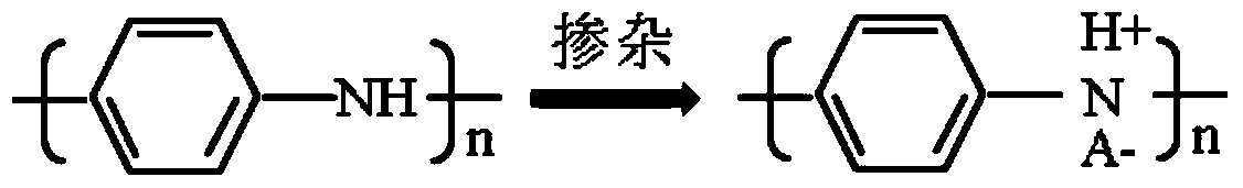
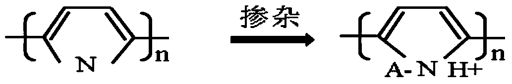
[0025] Next, the preparation method of the positive electrode sheet according to the second aspect of the present invention is described, which is used to prepare the positive electrode sheet of the first aspect of the present invention, comprising the steps of: (1) blending the conductive polymer material and the dopant by stirring and dispersing Obtain the undercoating slurry in a solvent, and then coat the undercoating slurry on the positive electrode current collector; (2) dissolve the positive electrode active material and the binder in the solvent to obtain the positive electrode slurry, and then apply the positive electrode slurry Coating on the undercoating slurry, followed by drying and compacting by a roller press to obtain a positive electrode sheet, wherein the undercoating slurry is dried to form an undercoat layer, and the positive electrode slurry is dried to form a positive electrode membrane.

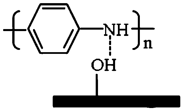
[0026] During the drying process of the slurry, the nitrogen atom o...

Embodiment 1

[0033] Dissolve 99.0wt% polyaniline, 0.5wt% dodecylbenzenesulfonic acid and 0.5wt% sodium polyacrylate in N-methylpyrrolidone (NMP) and disperse and stir at a high speed to obtain the undercoating slurry, and the undercoating slurry The solid content of the material is about 7%, the viscosity is 300mPa.s, and then the undercoating slurry is coated on the aluminum foil, and the coating thickness is controlled to be 1 μm to 6 μm to obtain the substrate J1 containing the undercoating layer.

Embodiment 2

[0035] Dissolve 98.5wt% of polypyrrole, 1wt% of dodecylbenzenesulfonic acid and 0.5wt% of sodium polyacrylate in NMP, disperse and stir at a high speed to obtain a primer slurry, and the solid content of the primer slurry is about 10% , with a viscosity of 1800 mPa.s, and then coating the undercoating slurry on the aluminum foil, controlling the coating thickness to be 2 μm to 10 μm to obtain the substrate J2 containing the undercoating layer.


PUM

PropertyMeasurementUnit
thicknessaaaaaaaaaa
viscosityaaaaaaaaaa
viscosityaaaaaaaaaa

Abstract

The invention provides a positive plate and a secondary battery. The positive plate comprises a positive current collector and a positive diaphragm which is located on the positive current collector and includes a positive active material and a binder, wherein a hydroxyl radical exists on the surface of the positive current collector; the binder comprises an organic polymer binder; the positive plate also comprises a bottom coating which is located between the positive current collector and the positive diaphragm; the bottom coating comprises a conductive polymer material and a dopant; the conductive polymer material contains the nitrogen element and is of a conjugated structure; and the dopant is protonic acid. The positive plate provided by the invention has relatively high binding power and electronic conductivity, and ensures that the secondary battery has lower internal resistance and higher safety performance.

Description

technical field [0001] The invention relates to the technical field of batteries, in particular to a positive electrode sheet and a secondary battery. Background technique [0002] The positive electrode layer of the battery is generally composed of a positive electrode active material, a conductive agent (such as conductive carbon) and a binder (such as PVDF). The way to increase conductivity is usually to increase the amount of conductive agent in the positive electrode formulation, and the way to improve the binding force is usually to increase the amount of binder in the positive electrode formulation. Increasing the amount of conductive agent can improve the electronic conductivity of the positive electrode, but it will lose the ratio of the positive active material, so that the content of the positive active material is relatively reduced, resulting in a decrease in energy density, and the increase of the conductive agent generally consumes less There is too much bind...

Claims


Application Information

Patent Timeline
Patent Type & Authority Patents(China)
IPC IPC(8): H01M4/13H01M4/36H01M4/62H01M4/64H01M10/0525H01M10/30
CPCH01M4/13H01M4/36H01M4/622H01M4/624H01M4/64H01M10/0525H01M10/30Y02E60/10
Inventor 张新亮李吉蓉
Owner NINGDE AMPEREX TECH
Why Eureka
Try Eureka