Carbon based electrocatalysts for fuel cells
Inactive Publication Date: 2010-06-24
RGT UNIV OF CALIFORNIA
25 Cites 54 Cited by
AI-Extracted Technical Summary
Problems solved by technology
However, carbon black does not provide sufficient simultaneous access of gas, proton, and electron.
In addition, membrane electrode assemblies (M...
Method used
[0064]Referring to FIG. 4, the most commonly used electrode catalyst 400 is platinum (Pt) 420, 425 supported on carbon fibers 410. One of the challenges in the commercialization of PEMFCs and DMFCs is the high cost of noble metals used as catalyst (e.g., platinum). Decreasing the amount of platinum used in a fuel cell electrode via the increase of the utilization efficiency of platinum has been one of the major concerns during the past decade. To effectively utilize the platinum catalyst, the platinum should have simultaneous access to the gas, the electron-conducting medium, and the proton-conducting medium. In the catalyst layer of a platinum-based conventional fuel cell prepared by the ink-process, the simultaneous access of the platinum particle 420 by the electron-conducting medium and the proton-conducting medium is achieved via a skillful blending of platinum supporting carbon black particles 430 and the solubilized perfluorosulfonate ionomer (e.g., NAFION) 450. The carbon particles conduct electrons and the perfluorosulfonate ionomer (e.g., NAFION) conduct protons.
[0066]Due to their unique structural, mechanical, and electrical properties, carbon nanotubes may be used to replace traditional carbon powders in PEMFCs and have been demonstrated by making membrane electrode assemblies (MEA) using carbon nanotube powders through a conventional ink process. The use of carbon nanotubes and the resulting guaranteed electronic pathway eliminate the previously mentioned problem with conventional PEMFC strategies where the proton-conducting medium (e.g., NAFION) would isolate the carbon particles in the electrode layer. Eliminating the isolation of the carbon particles supporting the electrode layer improves the utilization rate of platinum.
[0070]The present invention includes a filtration process for forming membrane electrode assembly films having carbon-based nanomaterials (for brevity, the process is described for carbon nanotubes, but is applicable to carbon nanofibers and stacked-cupped nanotubes). Carbon nanotubes (CNTs) have been studied as an electrocatalyst support for proton-exchange membrane fuel cells and direct methanol fuel cells. Some early investigations found that by using the normal paste method and simply replacing carbon black particles with disordered multi-walled CNTs as the support for platinum (Pt) catalyst nanoparticles higher PEMFC and DMFC performances were achieved. There was also an effort to form a single-walled carbon nanotube (SWNT) film via the electrophoretic method for studying the effect of SWNTs as a catalyst support in fuel cells.
[0071]It is believed that an oriented CNT film may offer much improved fuel cell performance over that of disordered CNTs because of its unique microstructure. First, the electronic conductivity of CNTs is much higher along the tubes than across the tubes, and there is no energy loss when electrons transfer along the tubes. Second, higher gas permeability is expected with the oriented CNT film. Third, an oriented film may also exhibit super-hydrophobicity, which can greatly facilitate water removal within the electrode, thereby improving mass transport in a PEMFC or DMFC.
[0072]Aligned multi-walled carbon nanotube (MWNTs) film have been grown directly on a carbon paper substrate by the chemical vapor deposition (CVD) method with subsequent deposition of platinum nanoparticles on the MWNTs to form the composite electrode. An advantage of the CVD approach is that the deposited platinum nanoparticles are almost guaranteed to be in electrical contact with the external circuit and much improved platinum utilization (e.g., sixty percent) has been achieved. With the aforementioned direct CVD method, however, it has been difficult thus far to prepare platinum catalyst nanoparticles with a uniform small diameter (e.g., less than five nanometers) at high platinum loading (e.g., thirty wt %), two critical properties of a high-performance electrocatalyst. Also, it has been found that it is difficult to grow an aligned CNT film directly on carbon paper by the CVD method because of the rough nature of the carbon paper. In addition, although the CVD process is well suited to the fabrication of micro fuel cells, the process is expensive to scale up if films with large areas (e.g., hundreds of cm2) are desired.
[0075]Suitable CNTs for use in the filtration method of the present invention include commercial products synthesized by the CVD method (for example, multi-walled carbon nanotubes available from Material & Electrochemical Research Corp.). To achieve a uniform platinum deposition on the outer walls of the nanotubes, the CNTs were surface oxidized by a 2.0 M H2SO4/4.0 M HNO3 mixture for six hours under refluxing conditions. The oxidized and washed CNTs were then suspended in ethylene glycol solution and mixed with hexachloroplatinic acid in ethylene glycol solution. After adjusting the pH of the solution to above thirteen with 1.0 M NaOH in ethylene glycol, the mixture was held at 140° C. for three hours under reflux conditions to reduce the platinum. After filtration, washing, and drying, a Pt/CNT catalyst metal loading of thirty weight percent (wt %) was obtained.
[0080]The contact angles (CA) of the oriented Pt/CNT film (FIG. 15A) and the non-oriented Pt/CNT film (FIG. 15B) (spraying Pt/CNT onto the cathode diffusion layer directly and without PTFE) are 151.7° and 134.2°, respectively. It is interesting that large contact angles are obtained even though these CNTs have been treated with a mixture of nitric acid and sulfuric acid before the platinum deposition. Apparently, hydrophilic functional groups (e.g., —COOH) were generated during the acid reflux process but may have been ...
Benefits of technology
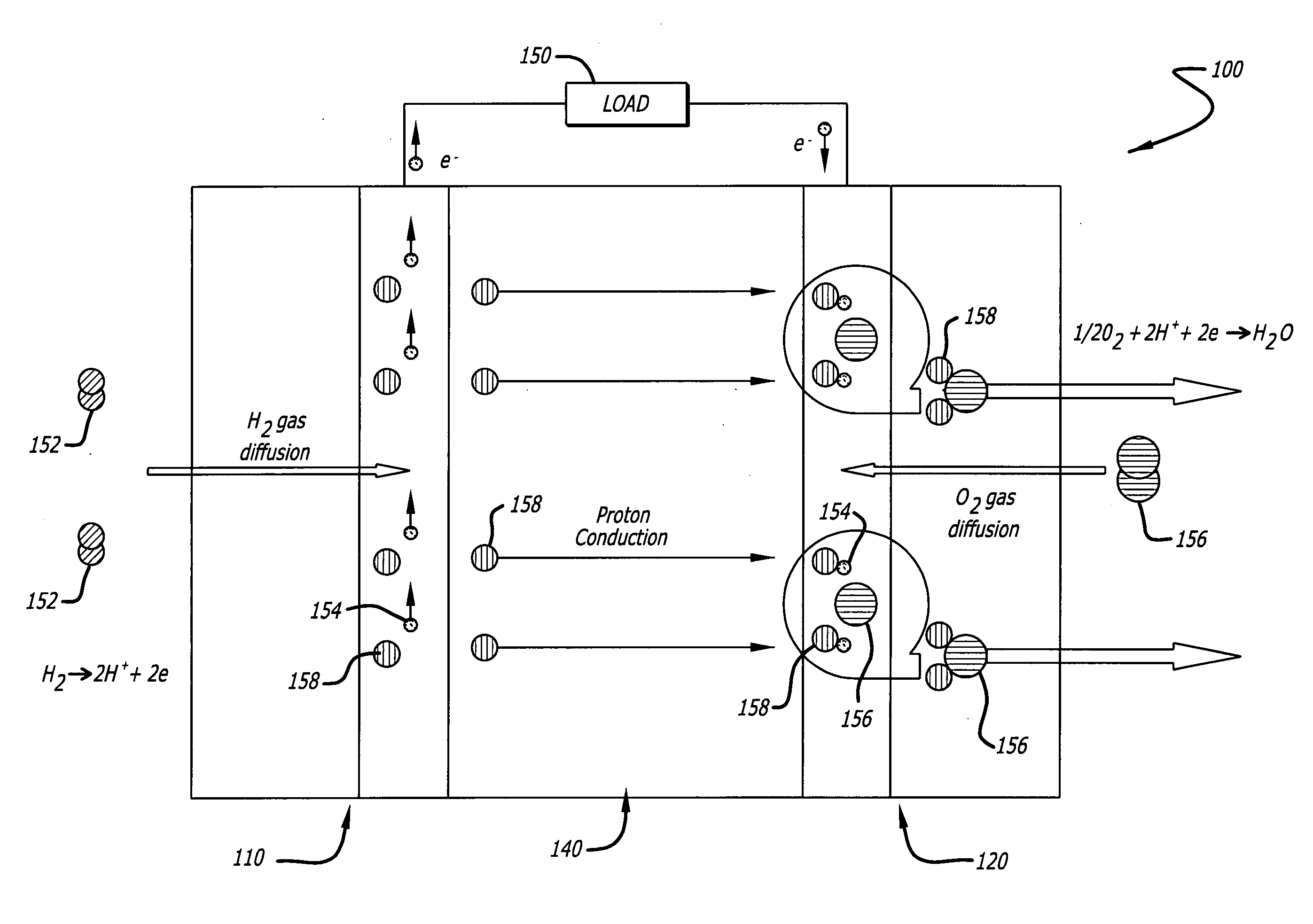
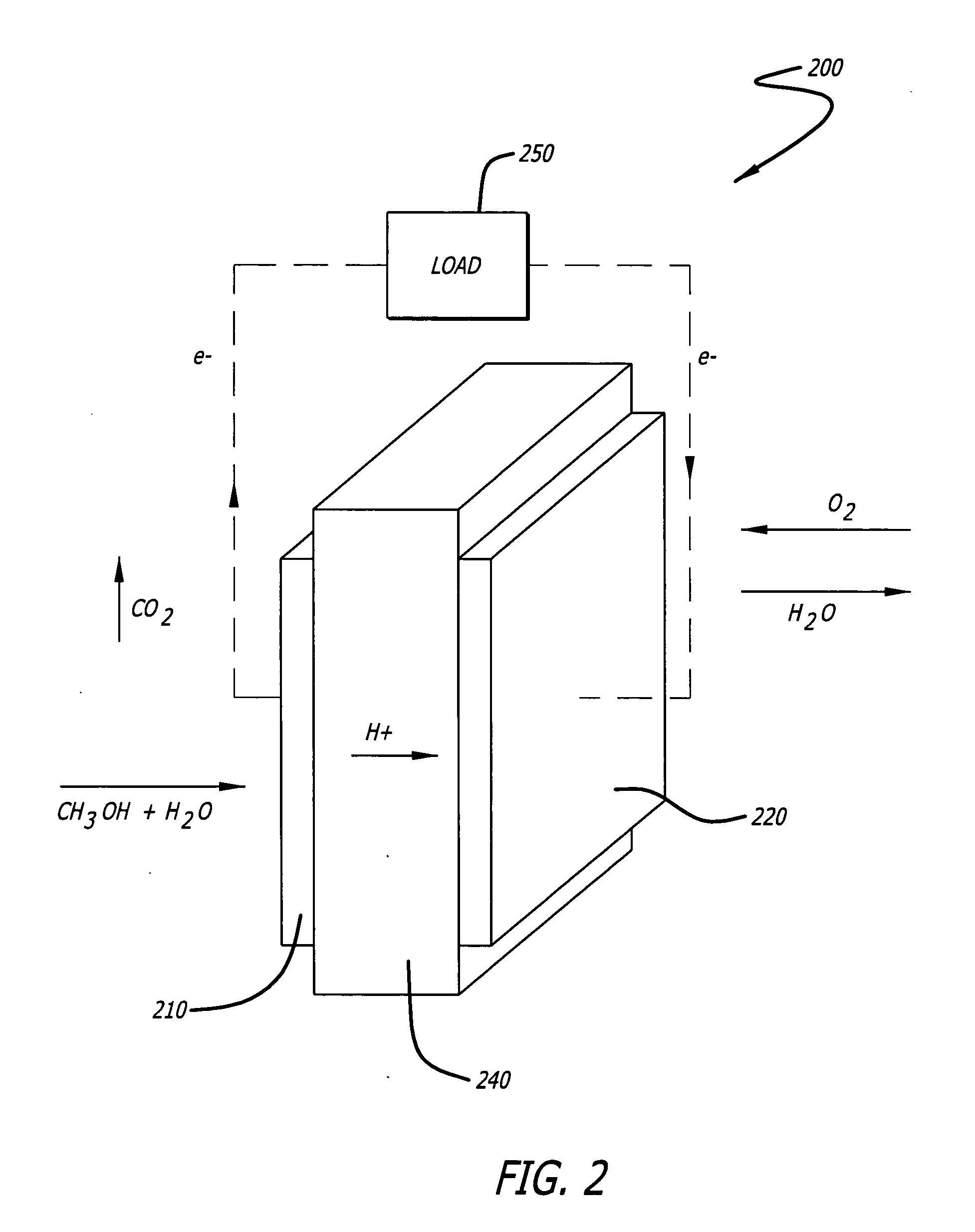
[0014]This invention provides a proton exchange membrane fuel cell with nanostructured components, in particular, the electrodes. The nanostructured fuel cell has a higher precious metal utilization rate at the electrodes, higher power density (kW/volume and kW/mass), and lower cost. The nanostructured fuel cells are not only attractive for stationary and mobile applications, but also for use as a compact power supply for microelectronics such as laptops, cell phones and other electronic gadgets. In accordance with one embodiments of the present invention, aligned (oriented) arrays of carbon nanotubes are used as support for catalyst. The aligned array of carbon nanotubes includes single-walled, dual-walled, multi-walled, and cup-stacked carbon nanotubes. The precious metal in the catalyst (e.g., platinum and ruthenium) is deposited using an ethylene glycol reduction method. After depositing precious metal(s), a solubilized perfluorosulfonate ionomer (e.g., NAFION) may be incorporated into the spare space between nanotubes to form a 4-phase boundary (gas, metal, proton conductor, and electron conductor). By assembling the as-prepared electrodes with a membrane, gas diffusion layers and electron collectors, a membrane electrode assembly is developed for incorporation into a fuel cell.
[0015]The common catalyst used in proton exchange membrane fuel cells incorporates carbon black as a support structure (FIG. 4). However, carbon black does not provide sufficient simultaneous access of gas, proton, and electron. In addition, membrane electrode assemblies (MEA) using carbon black provide low platinum utilization (20-30%), a dense catalyst layer, low catalys...
Abstract
Novel proton exchange membrane fuel cells and direct methanol fuel cells with nanostructured components are configured with higher precious metal utilization rate at the electrodes, higher power density, and lower cost. To form a catalyst, platinum or platinum-ruthenium nanoparticles are deposited onto carbon-based materials, for example, single-walled, dual-walled, multi-walled and cup-stacked carbon nanotubes. The deposition process includes an ethylene glycol reduction method. Aligned arrays of these carbon nanomaterials are prepared by filtering the nanomaterials with ethanol. A membrane electrode assembly is formed by sandwiching the catalyst between a proton exchange membrane and a diffusion layer that form a first electrode. The second electrode may be formed using a conventional catalyst. The several layers of the MEA are hot pressed to form an integrated unit. Proton exchange membrane fuel cells and direct methanol fuel cells are developed by stacking the membrane electrode assemblies in a conventional manner.
Application Domain
Active material electrodesCoatings +2
Technology Topic
Hot pressPrecious metal +20
Image
Examples
- Experimental program(1)
Example
Example 1
Single-Walled Carbon Nanotubes
Process A:
[0105] 1) Weigh SWNTs 1.00 g, put it into flask (250 mL with 3 necks); [0106] 2) Add 120 mL 2M H2SO4+4M HNO3 into the flask, stir it at 1000 rpm for 10 minutes (min) at room temperature; [0107] 3) Ultrasonicate it for another 20 min; [0108] 4) Put the flask in a mantle heater (1000 rpm), increasing temperature to 110° C. for eight hours; [0109] 5) Dilute the solvent by adding another 200 mL DI water in the above-mentioned flask; [0110] 6) Filtrate it by normal filter paper and then by copious water (1 L hot DI water, 85° C.) in batches; [0111] 7) Put the funnel with the filter paper and filtrate cake into a convection oven at 110° C. for eight hours; [0112] 8) After drying, put the support into a glass bottle for later use.
Process B:
[0113] 1) Weigh SWNTs 1.00 g, put it into the flask (500 mL with 3 necks); [0114] 2) Add 150 mL EG into the flask and stir it for 10 min; [0115] 3) Ultrasonicate it for another 20 min (suspension becomes ink); [0116] 4) Put the flask in a heating mantle (hot plate/stirrer) and set the stirring rate of 1000 rpm (the following procedures are all under stirring); [0117] 5) Add 0.75 g H2PtCl6.xH2O (37.5% Pt) and 0.29 g RuCl3 (48.3% Ru) in 30 mL EG by dropping (using funnel); [0118] 6) Let N2 go through the flask and stir for 30 min, the following procedures are all under N2 protection; [0119] 7) Add 22 mL 1.0 M NaOH by dropping (using funnel) into the flask to make pH=13; [0120] 8) Stir for another 30 min; [0121] 9) Increase the heating mantle's temperature to 135° C. in 15 min; [0122] 10) Keep flask under refluxing at the temperature (135° C.) for 3 h with 1000 rpm; [0123] 11) Cool down the flask naturally, keep at room temperature for one hour with 1000 rpm; [0124] 12) Add 200 mL DI water into the flask; [0125] 13) Add 10 mL 2 M HCl by dropping (using funnel) into the flask to make the pH=3; [0126] 14) Keep Stirring for 1.0 hour; [0127] 15) Stop stirring and wait for 1.0 hour; [0128] 16) Filtrate the PtRu/SWNTs (30 wt % Pt—Ru) solid with a regular filter paper (Grade No. 3), diameter 4 cm, wash it by 1 L hot DI water at 85° C.; [0129] 17) Put the funnel with the filter paper and filtrate cake into a vacuum oven at 85° C. for eight hours; [0130] 18) After drying, put the catalyst into a bottle for later use.
Process C:
[0131] 1) Weigh PtRu/SWNTs 42 mg, put it into flask; [0132] 2) Add a drop of H2O to wet PtRu/SWNTs; [0133] 3) Add 10 mL ethanol and 362 mg NAFION (5 wt %); [0134] 4) Ultrasonic treating for 20 min, in order to make it become ink; [0135] 5) Put a normal filter paper first, and then put a Nylon paper (2 cm in diameter) in the funnel, drop 1 mL ethanol to wet the paper; [0136] 6) Add the ink into the funnel; [0137] 7) Filter the ink to get a black solid onto the Nylon paper; [0138] 8) Weigh 420 mg NAFION solution (5 wt %) in a 50 mL beaker and dilute it by same volume of ethanol, ultrasonic for 5 min; [0139] 9) Spraying the NAFION solution to surface of PtRu/SWNTs deposited onto the Nylon filter, and drying it naturally in the hood for 20 mins; [0140] 10) Cut the filter paper with PtRu/SWNTs catalyst into 1 piece of 2.0*2.0 cm2; [0141] 11) Hot-pressing an anode, NAFION 115 membrane and a piece of filter paper with PtRu/SWNTs at 120° C., 0.15 metric tons for 15 seconds; [0142] 12) Carefully peel the filter paper off; [0143] 13) Put the PtRu/SWNTs coated NAFION 115 membrane in a plastic bag for MEA preparation; [0144] 14) Hot pressing a cathode and the PtRu/SWNTs coated NAFION 115 membrane at 135° C., 1.2 metric tons for 1.5 min.
Example No. 2
Dual-Walled Carbon Nanotubes
Process A:
[0145] 1) Weigh DWNTs 1.00 g, put it into flask (250 mL with 3 necks); [0146] 2) Add 120 mL 2 M H2SO4+4 M HNO3 into the flask, stir it at 1000 rpm for 10 min at room temperature; [0147] 3) Ultrasonicate it for another 20 min; [0148] 4) Put the flask in a mantle heater (1000 rpm), increasing temperature to 110° C. for eight hours; [0149] 5) Dilute the solvent by adding another 200 mL DI water in the above mentioned flask; [0150] 6) Filtrate it by normal filter paper and then by copious water (1 L hot DI water, 85° C.) in batches; [0151] 7) Put the funnel with the filter paper and filtrate cake into a convection oven at 110° C. for eight hours; [0152] 8) After drying, put the support into a glass vial for later use.
Process B:
[0153] 1) Weigh DWNTs 1.00 g, put it into the flask (500 mL with 3 necks); [0154] 2) Add 150 mL EG into the flask and stir it for 10 min; [0155] 3) Ultrasonicate it for another 20 min (suspension becomes ink); [0156] 4) Put the flask in a heating mantle (hot plate/stirrer) and set the stirring rate of 1000 rpm (the following procedures are all under stirring); [0157] 5) Add 0.75 g H2PtCl6.xH2O (37.5% Pt) and 0.29 g RuCl3 (48.3% Ru) in 30 mL EG by dropping (using funnel); [0158] 6) Let N2 go through the flask and stir for 30 min, the following procedures are all under N2 protection; [0159] 7) Add 22 mL 1.0 M NaOH by dropping (using funnel) into the flask to make pH=13; [0160] 8) Stir for another 30 min; [0161] 9) Increase the heating mantle's temperature to 135° C. in 15 min; [0162] 10) Keep flask under refluxing at the temperature of 135° for three hours with 1000 rpm; [0163] 11) Cool down the flask naturally, keep at room temperature for one hour with 1000 rpm; [0164] 12) Add 200 mL DI water into the flask; [0165] 13) Add 10 mL 2 M HCl by dropping (using funnel) into the flask to make the pH=3; [0166] 14) Keep Stirring for 1.0 hour; [0167] 15) Stop stirring and wait for 1.0 hour; [0168] 16) Filtrate the PtRu/DWNTs (30 wt % Pt—Ru) solid with a regular filter paper (Grade No. 3) diameter 4 cm, wash it by 1 L hot DI water (85° C.); [0169] 17) Put the funnel with the filter paper and filtrate cake into a vacuum oven at 85° C. for eight hours; [0170] 18) After drying, put the catalyst into a bottle for later use.
Process C:
[0171] 1) Weigh PtRu/DWNTs 21 mg, put it into flask; [0172] 2) Add a drop of H2O to wet PtRu/DWNTs; [0173] 3) Add 5.5 mL ethanol and 180 mg NAFION (5 wt %); [0174] 4) Ultrasonic treating for 20 min, in order to make it become ink; [0175] 5) Put a normal paper first, and then put a Nylon paper (4 cm in diameter) in the funnel, drop 1 mL ethanol to wet the paper; [0176] 6) Add the ink into the funnel; [0177] 7) Weigh 123 mg NAFION (5 wt %), and dilute it with same volume of ethanol and then put into airbrush; [0178] 8) Filter the ink to get a black solid onto the Nylon paper gradually by 5 times, after one time, spray NAFION on the top of the filtrate cake; [0179] 9) Weigh 210 mg NAFION solution (5 wt %) in a 50 mL beaker and dilute by same volume of ethanol, ultrasonic for 5 min; [0180] 10) Spraying the NAFION solution to surface of PtRu/DWNTs deposited onto the Nylon filter paper, and drying it naturally in the hood for 20 mins; [0181] 11) Cut the filter paper with PtRu/DWNTs catalyst into 1 piece of 2.0*2.0 cm2; [0182] 12) Hot-pressing an anode, NAFION 115 membrane and a piece of filter paper with PtRu/DWNTs at 120° C., 0.15 metric tons for 15 seconds; [0183] 13) Carefully peel the filter paper off; [0184] 14) Put the PtRu/DWNTs coated NAFION 115 membrane in a plastic bag for MEA preparation; [0185] 15) Hot pressing a cathode and the PtRu/DWNTs coated NAFION 115 membrane at 135° C., 1.2 metric tons for 1.5 min.
Example No. 3
Cup-Stacked Carbon Nanotubes
Process A:
[0186] 1) Weigh CS-CNTs 1.00 g, put it into flask (250 mL with 3 necks); [0187] 2) Add 120 mL 2M H2SO4+4M HNO3 into the flask, stir it at 1000 rpm for 10 min at room temperature; [0188] 3) Ultrasonicate it for another 20 min; [0189] 4) Put the flask in a mantle heater (1000 rpm), increasing temperature to 110° C. for eight hours; [0190] 5) Dilute the solvent by adding another 200 mL DI water in the above mentioned flask; [0191] 6) Filtrate it by normal filter paper and then by copious water (1 L hot DI water, 85° C.) in batches; [0192] 7) Put the funnel with the filter paper and filtrate cake into a conventional oven at 110° C. for eight hours; [0193] 8) After drying, put the support into a glass bottle for later use.
Process B:
[0194] 1) Weigh CS-CNTs 1.00 g, put it into the flask (500 mL with 3 necks); [0195] 2) Add 150 mL EG into the flask and stir it for 10 min; [0196] 3) Ultrasonicate it for another 20 min (suspension becomes ink); [0197] 4) Put the flask in a heating mantle (hot plate/stirrer) and set the stirring rate of 1000 rpm (the following procedures are all under stirring); [0198] 5) Add 1.14 g H2PtCl6.xH2O (37.5% Pt) in 30 mL EG by dropping (using funnel); [0199] 6) Let N2 go through the flask and stir for 30 min, the following procedures are all under N2 protection; [0200] 7) Add 22 mL 1.0 M NaOH by dropping (using funnel) into the flask to make pH=13; [0201] 8) Stir for another 30 min; [0202] 9) Increase the heating mantle's temperature to 135° C. in 15 min; [0203] 10) Keep flask under refluxing at the temperature (135° C.) for three hours with 1000 rpm; [0204] 11) Cool down the flask naturally, keep at room temperature for one hour with 1000 rpm; [0205] 12) Add 200 mL DI water into the flask; [0206] 13) Add 10 mL 2 M HCl by dropping (using funnel) into the flask to make the pH=3; [0207] 14) Keep Stirring for 1.0 hour; [0208] 15) Stop stirring and wait for 1.0 hour; [0209] 16) Filtrate the Pt/CS-CNTs (30 wt % Pt) solid with a regular filter paper (Grade No. 3) diameter 4 cm, wash it by 1 L hot DI water (85° C.); [0210] 17) Put the funnel with the filter paper and filtrate cake into a vacuum oven at 85° C. for eight hours; [0211] 18) After drying, put the catalyst into a bottle for later use.
Process C:
[0212] 1) Weigh Pt/CS-CNTs 153 mg, put it into flask; [0213] 2) Add a drop of H2O to wet Pt/CS-CNTs; [0214] 3) Add 5.5 mL ethanol; [0215] 4) Ultrasonic treating for 20 min, in order to make it become ink; [0216] 5) Put a normal paper before the special paper first, and then put a Nylon paper (4 cm in diameter) in the funnel, drop 10 mL ethanol to wet the paper; [0217] 6) Add the catalyst ink into the funnel; [0218] 7) Filter the ink to get a black solid onto the Nylon paper; [0219] 8) Weigh 1.53 g NAFION solution (5 wt %) in a 100 mL beaker and dilute by a 100 mL of ethanol, ultrasonic for 5 min; [0220] 9) Spraying the NAFION solution to surface of Pt/CS-CNTs deposited onto the Nylon filter, and drying it naturally in the hood for 20 mins; [0221] 10) Cut the filter paper with Pt/CS-CNTs catalyst into 1 piece of 2×2 cm2; [0222] 11) Hot-pressing an anode, NAFION 115 membrane and a piece of filter paper with Pt/CS-CNTs at 120° C., 0.15 metric tons for 15 secs; [0223] 12) Carefully peel the filter paper off; [0224] 13) Put the Pt/CS-CNTs coated NAFION 115 membrane in a plastic bag for MEA preparation; [0225] 14) Hot pressing a cathode and the Pt/CS-CNTs coated NAFION 115 membrane at 135° C., 1.2 metric tons for 1.5 min.
[0226]While particular forms of the invention have been illustrated and described, it will also be apparent to those skilled in the art that various modifications can be made without departing from the inventive concept. References to use of the invention with a membrane electrode assembly and fuel cell are by way of example only, and the described embodiments are to be considered in all respects only as illustrative and not restrictive. The present invention may be embodied in other specific forms without departing from its spirit or essential characteristics. Accordingly, it is not intended that the invention be limited except by the appended claims.
PUM


Description & Claims & Application Information
We can also present the details of the Description, Claims and Application information to help users get a comprehensive understanding of the technical details of the patent, such as background art, summary of invention, brief description of drawings, description of embodiments, and other original content. On the other hand, users can also determine the specific scope of protection of the technology through the list of claims; as well as understand the changes in the life cycle of the technology with the presentation of the patent timeline. Login to view more.
Similar technology patents
Zero Voltage Switching Flying Capacitor Power Converters
Owner:WITTENBREDER JR ERNEST HENRY
Power Semiconductor Module
ActiveUS20160027762A1delay switch behaviorhigh power density
Owner:HITACHI ENERGY SWITZERLAND AG
Modal discriminating and linearly polarized fiber lasers
InactiveUS6801549B1high laser powerhigh power density
Owner:PC PHOTONICS CORP
Method of decomposing gypsum to sulfur dioxide and the apparatus thereof
InactiveUS20050100503A1high utilization ratehigh concentration
Owner:SHANDONG LUBEI ENTERPRISE GROUP
Power saving device and all-in-one PC having the same
Owner:MSI COMP SHENZHEN
Magnetostriction element and magnetostriction-type vibration powered generator using same
PendingUS20210242809A1large power outputhigh power density
Owner:PANASONIC INTELLECTUAL PROPERTY MANAGEMENT CO LTD
Classification and recommendation of technical efficacy words
- high utilization rate
- high power density
Method of decomposing gypsum to sulfur dioxide and the apparatus thereof
InactiveUS20050100503A1high utilization ratehigh concentration
Owner:SHANDONG LUBEI ENTERPRISE GROUP
High power-density, high efficiency, non-permanent magnet electric machine
Owner:GENERAL ELECTRIC CO
Zero Voltage Switching Flying Capacitor Power Converters
Owner:WITTENBREDER JR ERNEST HENRY
Power saving device and all-in-one PC having the same
Owner:MSI COMP SHENZHEN
Modal discriminating and linearly polarized fiber lasers
InactiveUS6801549B1high laser powerhigh power density
Owner:PC PHOTONICS CORP