Method for manufacturing antenna on glass back cover and glass back cover equipped with antenna

A glass and antenna technology, applied in the field of electronic equipment, can solve the problem that the size and accuracy of the antenna needs to be improved, and achieve the effects of rich and changeable shapes, high production efficiency, and better communication effects.

Active Publication Date: 2017-05-31
LENS TECH CHANGSHA
View PDF5 Cites 8 Cited by
  • Summary
  • Abstract
  • Description
  • Claims
  • Application Information

AI Technical Summary

Problems solved by technology

In the prior art, there is an antenna integrated on the glass back cover by printing, but this method is only suitable for the flat glass back cover, and it is difficult to

Method used


Image

  • Method for manufacturing antenna on glass back cover and glass back cover equipped with antenna

Examples


Embodiment 1

[0032] This embodiment provides a planar 2D glass back cover with an antenna, which is manufactured by the following steps.

[0033] S1. Spray a conductive paste layer on the protective ink layer of the glass back cover.

[0034] The conductive paste layer is produced by spraying photosensitive silver paste on the protective ink layer of the flat 2D glass back cover. The photosensitive silver paste includes 70wt% of silver powder and 30wt% of binder, and its viscosity is 1000-1500cps.

[0035] The entire spraying operation is carried out at a temperature of 40° C. and a pressure of 0.1 MPa. The surface on which the antenna will be installed is sprayed on the front, and the number of sprays is 1 to 3 times until a uniform and flat conductive paste layer is obtained.

[0036] After the spraying of the conductive paste layer is completed, the conductive paste layer is baked at 120° C. for 30 minutes. Until the shape of the conductive paste layer is basically fixed.

[0037] S2....

Embodiment 2

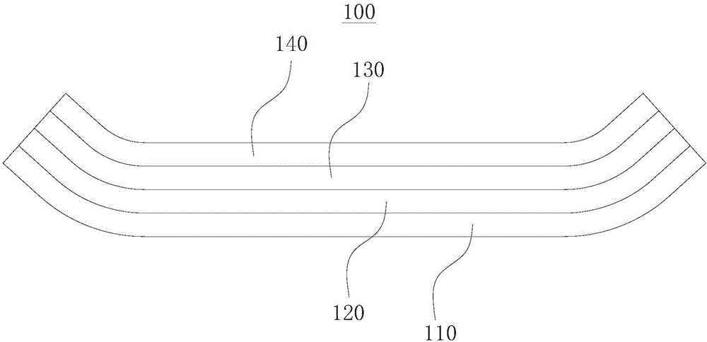
[0042] This embodiment provides a curved 2.5D glass back cover with an antenna, which is manufactured by the following steps.

[0043] S1. Spray a conductive paste layer on the protective ink layer of the glass back cover.

[0044] The conductive paste layer is produced by spraying photosensitive silver paste on the protective ink layer of the curved 2.5D glass back cover. The photosensitive silver paste includes 85wt% of silver powder and 15wt% of binder, and its viscosity is 500-1000cps.

[0045] The entire spraying operation is carried out at a temperature of 40° C. and a pressure of 0.3 MPa. The surface on which the antenna will be installed is sprayed on the front, and the number of sprays is 1 to 3 times until a uniform and flat conductive paste layer is obtained.

[0046] After the spraying of the conductive paste layer is completed, the conductive paste layer is baked at 150° C. for 10 minutes. Until the shape of the conductive paste layer is basically fixed.

[00...

Embodiment 3

[0052] This embodiment provides a four-sided curved 3D glass back cover with an antenna, which is manufactured by the following steps.

[0053] S1. Spray a conductive paste layer on the protective ink layer of the glass back cover.

[0054] The conductive paste layer is produced by spraying photosensitive silver paste on the protective ink layer of the four-sided curved 3D glass back cover. The photosensitive silver paste includes 50wt% of silver powder and 50wt% of binder, and its viscosity is 2500-3000cps.

[0055] The entire spraying operation is carried out at a temperature of 40° C. and a pressure of 0.8 MPa. The surface on which the antenna will be installed is sprayed on the front, and the number of sprays is 1 to 3 times until a uniform and flat conductive paste layer is obtained.

[0056] After the spraying of the conductive paste layer is completed, the conductive paste layer is baked at 100° C. for 30 minutes. Until the shape of the conductive paste layer is basi...


PUM

PropertyMeasurementUnit
Viscosityaaaaaaaaaa
Square resistanceaaaaaaaaaa
Depth of stress layeraaaaaaaaaa

Abstract

The invention discloses a method for manufacturing an antenna on a glass back cover, and belongs to the field of electronic equipment. The method comprises the steps of spraying a protective ink layer on the glass back cover with a conductive slurry layer; forming the conductive slurry layer into to an antenna loop in a portraying manner; and covering the antenna loop with an insulating coating layer. By adoption of the method, the glass back cover is successfully integrated with the antenna function; the binding force between the photosensitive conductive slurry and the glass back cover is strong, so that the finished glass back cover can be directly sprayed with the conductive slurry without adding other transitional layer; by virtue of the method, the antenna loop can be accurately portrayed, and compared with the conventional printing process, the dimensional precision of the antenna is higher; and meanwhile, the process is not limited by the shape of the glass back cover, so that setting of the antenna on a plane, a cambered surface, a four-side hook face and a two-side hook surface can be realized, and the application range is extremely wide. The invention also provides the glass back cover equipped with the antenna; the glass back cover is integrated with the antenna function by adoption the method; and the glass back cover has the characteristics of lighter and thinner appearance, better communication effect, rich and diversified shapes and the like.

Description

technical field [0001] The invention relates to the field of electronic equipment, in particular to a method for manufacturing an antenna on a glass back cover and a glass back cover with the antenna. Background technique [0002] Antenna design occupies a very important position in the design of terminal products, and is a very important part that affects consumer experience. Conventional antenna structures include bracket type and attached type. The bracket antenna is composed of a plastic bracket and a metal sheet (radiator). The metal sheet and the plastic bracket are fixed by hot melting. The plastic is usually made of ABS and PC materials, and the metal is usually made of copper-plated, phosphor bronze, stainless steel, etc. Adding two PINs on the top is costly; the attached antenna attaches the metal sheet (radiator) to the back shell of the product, and the fixing method generally adopts a hot-melt structure, or it can also be connected by adhesive. [0003] In the ...

Claims


Application Information

Patent Timeline
IPC IPC(8): H01Q1/38H01Q1/40H01Q1/44
CPCH01Q1/38H01Q1/40H01Q1/44
Inventor 周群飞饶桥兵林荣丰孟敬
Owner LENS TECH CHANGSHA
Why Eureka
Try Eureka