

Torque pulse suppression method of brushless DC motor in all speed regulation range
A technology of brush DC motor and pulsation suppression, which is applied in the direction of torque pulsation control, etc., can solve the problems of different current change rates, increased system calculation costs, and poor motor performance, so as to suppress torque pulsation, optimize control costs, and reduce The effect of controlling costs
- Summary
- Abstract
- Description
- Claims
- Application Information
AI Technical Summary
Problems solved by technology
Method used
Image

Examples
Embodiment Construction
[0043] The present invention will be further described below in conjunction with embodiment and accompanying drawing.
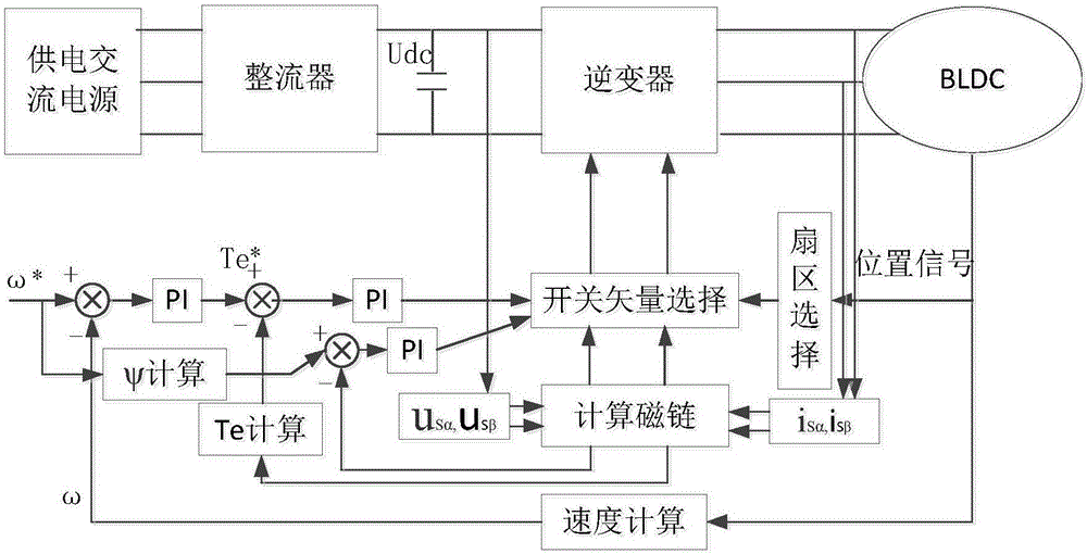
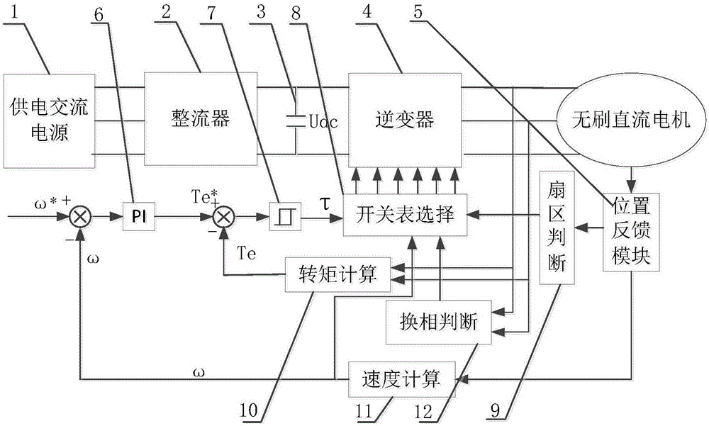
[0044] When the present invention is applied to supply power to a brushless DC motor, the AC power supply 1 is firstly rectified by the rectifier 2, then filtered by the filter capacitor 3 to obtain a DC power supply, and finally the DC power supply is converted into an AC power supply by the inverter 4 To supply power to the brushless DC motor, the torque ripple control method in the full speed regulation range of the brushless DC motor of the present invention is as follows:
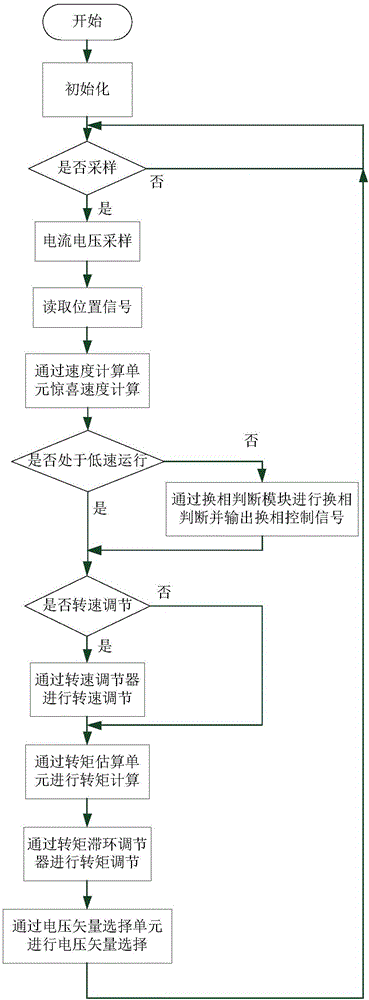
[0045] According to the motor speed obtained by the speed calculation module 12, it is divided into two states of low-speed operation and high-speed operation for corresponding control:
[0046] ① When the motor is running at low speed, the position feedback module 5 is used to detect the rotor angular velocity signal of the brushless DC motor, and the speed calculation module 11 is u...
PUM
 Abstract
Description
Claims
Application Information