Control method for ammonia spraying amount of denitration device and control device thereof

A control method and the technology of ammonia injection amount, applied in various fluid ratio control, injection devices, separation methods, etc., can solve the problems that the denitrification efficiency cannot guarantee the amount of ammonia escape, and the denitrification efficiency cannot meet expectations, so as to achieve accurate adjustment process And stable, eliminate residual error, save energy

Active Publication Date: 2017-06-06
SHANGHAI LONGKING ENVIRONMENTAL PROTECTION
View PDF7 Cites 11 Cited by
  • Summary
  • Abstract
  • Description
  • Claims
  • Application Information

AI Technical Summary

Problems solved by technology

[0011] The technical problem to be solved by the present invention is that the denitrification efficiency in the pr

Method used


Image

  • Control method for ammonia spraying amount of denitration device and control device thereof
  • Control method for ammonia spraying amount of denitration device and control device thereof
  • Control method for ammonia spraying amount of denitration device and control device thereof

Examples


Embodiment 1

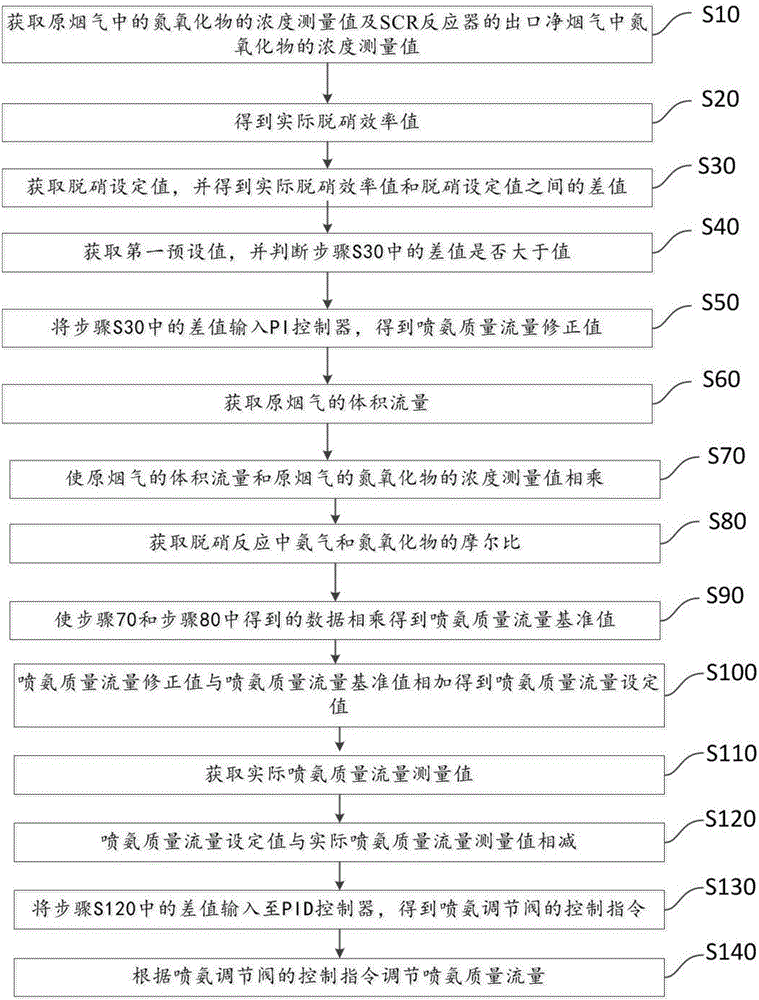
[0040] to combine figure 1 and figure 2 As shown, this embodiment 1 discloses a method for controlling the amount of ammonia sprayed by a denitrification device. The plate catalyst used in this embodiment is a vanadium-titanium-tungsten catalyst, and its main components include titanium dioxide, vanadium pentoxide, and tungsten trioxide. In the present invention, two layers of the catalyst are provided.

[0041] S10: Obtain the NO in the raw flue gas before entering the SCR reactor through the measurement of the first acquisition module 1 x The measured concentration is 355.1mg / Nm 3 NO in the net flue gas at the outlet of the SCR reactor x The measured concentration is 79.05mg / Nm 3 ;

[0042] S20: The NO in the raw flue gas obtained in the first acquisition module 1 x Concentration measurement value and NO in net flue gas x The actual denitrification efficiency value calculated from the concentration measurement value is 77.74%;

[0043] S30: Obtain the set value of t...

Embodiment 2 12

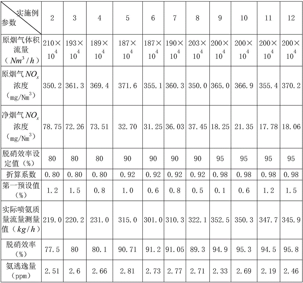
[0057] Table 1 shows eleven specific examples obtained according to the method in Example 1. Please refer to Table 1 for specific test parameters and results.

[0058] Table 1

[0059]

[0060] It can be seen from Table 1 that after adjusting the amount of ammonia injection by the method in the first embodiment, the denitrification efficiency is effectively guaranteed, and the amount of ammonia escape is controlled below 3ppm.

Embodiment 13

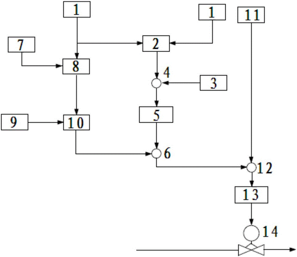
[0062] Such as figure 2 As shown, this embodiment discloses a control device for the amount of ammonia sprayed by a denitrification device. The control device includes: a first acquisition module 1 for obtaining NO in the raw flue gas at the entrance of the SCR reactor x The concentration measured value and the NO in the net flue gas at the outlet of the SCR reactor x Concentration measurement value; the first calculation module 2, connected with the first acquisition module 1, through the NO in the original flue gas x Concentration measurement value and NO in net flue gas x The concentration measurement value is calculated to obtain the actual denitration efficiency value; the second acquisition module 3 is used to obtain the denitration efficiency set value; the second calculation module 4 is connected to the first calculation module 2 and the second acquisition module 3 respectively, and is used for calculation to obtain The difference between the denitrification efficie...


PUM


Abstract

The invention discloses a control method for ammonia spraying amount of a denitration device and a control device of the control method for the ammonia spraying amount of the denitration device. According to the control method, the difference value of the actual denitration efficiency value and a denitrification efficiency set value is compared with a first preset value to judge whether the ammonia spraying mass flow rate should be adjusted or not, if yes, the difference value of the actual denitration efficiency value and the denitrification efficiency set value is input to a PI controller to obtain a corrected value of the ammonia spraying mass flow rate, then the corrected value of the ammonia spraying mass flow rate is added to a reference value of the ammonia spraying mass flow rate to obtain a set value of the spraying ammonia mass flow rate, the difference value of the set value of the spraying ammonia mass flow rate and a measured value of the actual ammonia spraying mass flow rate is input to the PID controller to obtain a control instruction of an ammonia spraying control valve to control the ammonia spraying control valve so as to adjust the ammonia spraying mass flow rate. The control method for the ammonia spraying amount of the denitration device disclosed by the invention is simple, adjusted accurately, capable of ensuring the denitration efficiency to reach an expected value, and further can make the ammonia escape amount reduced below 3ppm.

Description

technical field [0001] The invention relates to the field of controlling the amount of ammonia injection for denitrification, in particular to a method for controlling the amount of ammonia injection for a denitrification device and a control device thereof. Background technique [0002] With the development of our country's economy, the environmental pollution caused by energy consumption is becoming more and more serious. Among them, atmospheric smoke and dust, acid rain, greenhouse effect and destruction of the ozone layer have become the four major killers that endanger people's survival. Harmful substances such as soot, sulfur dioxide, and nitrogen oxides contained in coal-burning flue gas are the main sources of air pollution, acid rain, and greenhouse effect. In my country, harmful substances such as sulfur dioxide and nitrogen oxides are mainly produced by coal combustion. At present, my country has carried out large-scale flue gas desulfurization projects, but flu...

Claims


Application Information

Patent Timeline
IPC IPC(8): B01D53/76B01D53/56B01D53/86B05B12/00G05D11/13
Inventor 陈天光吴文辉
Owner SHANGHAI LONGKING ENVIRONMENTAL PROTECTION
Why Eureka
Try Eureka