Comprehensive smoke treatment device and method
A comprehensive treatment and flue gas technology, applied in the direction of combustion method, combustion product treatment, reduction of greenhouse gases, etc., can solve the problems of single realization, achieve the effect of improving thermal efficiency, efficient utilization, and improving safety and reliability
- Summary
- Abstract
- Description
- Claims
- Application Information
AI Technical Summary
Problems solved by technology
Method used
Image

Examples
Embodiment 1
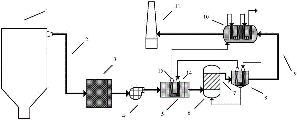
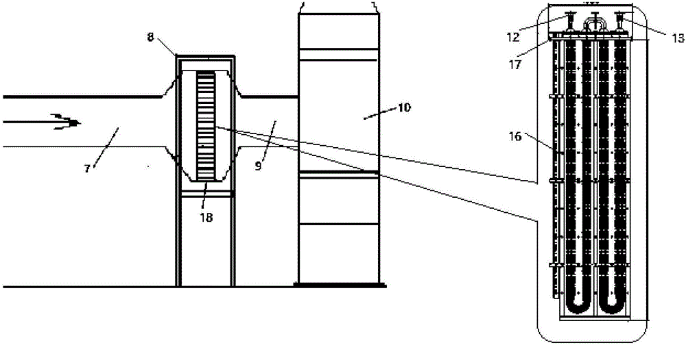
[0031] A flue gas comprehensive treatment device, including a boiler 1 connected in sequence, a tail flue 2, a dry dust collector 3, two induced draft fans 4 connected in parallel, a waste heat recovery heat exchanger 5 (shell-and-tube structure), and a desulfurization absorption tower 6. Outlet flue of desulfurization tower 7, phase change coagulation dust collector 8 (shell-and-tube structure), phase-change coalescence dust collector outlet flue 9, intermediate heat medium flue gas heat exchanger 10 (shell-and-tube structure) and chimney 11 , the phase change coagulation dust collector 8 includes a group of U-shaped tube bundle heat exchange tubes 16 (the heat exchange tube material is polytetrafluoroethylene, The center distance of the tube bundle is 30 mm), the tube plate 17 and the water collection device 18, the heat exchange tube 16 is arranged on the tube plate 17, the heat exchange tube 16 is provided with the desalted water inlet 12 of the phase change device and the...
Embodiment 2
[0037] A flue gas comprehensive treatment device, including a boiler 1 connected in sequence, a tail flue 2, a dry dust collector 3, two induced draft fans 4 connected in parallel, a waste heat recovery heat exchanger 5 (shell-and-tube structure), and a desulfurization absorption tower 6. Outlet flue of desulfurization tower 7, phase change coagulation dust collector 8 (shell-and-tube structure), phase-change coalescence dust collector outlet flue 9, intermediate heat medium flue gas heat exchanger 10 (shell-and-tube structure) and chimney 11 , the phase change coagulation dust collector 8 includes two sets of U-shaped tube bundle heat exchange tubes 16 (the heat exchange tube material is polytetrafluoroethylene, Tube bundle center distance is 28mm), tube sheet 17 and water collection device 18, two sets of U-shaped tube bundle heat exchange tubes 16 are all arranged on the tube sheet 17, and the heat exchange tubes 16 are provided with phase change device desalted water inlet...
Embodiment 3
[0043] A flue gas comprehensive treatment device, including a boiler 1 connected in sequence, a tail flue 2, a dry dust collector 3, two induced draft fans 4 connected in parallel, a waste heat recovery heat exchanger 5 (shell-and-tube structure), and a desulfurization absorption tower 6. Outlet flue of desulfurization tower 7, phase change coagulation dust collector 8 (shell-and-tube structure), phase-change coalescence dust collector outlet flue 9, intermediate heat medium flue gas heat exchanger 10 (shell-and-tube structure) and chimney 11 , the phase change coagulation dust collector 8 includes three sets of U-shaped tube bundle heat exchange tubes 16 (the heat exchange tube material is polytetrafluoroethylene, Tube bundle center distance is 24mm), tube sheet 17 and water collection device 18, three sets of U-shaped tube bundle heat exchange tubes 16 are all arranged on the tube sheet 17, and the heat exchange tubes 16 are provided with phase change device desalted water i...
PUM
 Abstract
Description
Claims
Application Information
 - R&D
- Intellectual Property
- Life Sciences
- Materials
- Tech Scout
- Unparalleled Data Quality
- Higher Quality Content
- 60% Fewer Hallucinations
Browse by: Latest US Patents, China's latest patents, Technical Efficacy Thesaurus, Application Domain, Technology Topic, Popular Technical Reports.
© 2025 PatSnap. All rights reserved.Legal|Privacy policy|Modern Slavery Act Transparency Statement|Sitemap|About US| Contact US: help@patsnap.com