Vacuum coating cavity leak detection system and leak detection method

A technology of vacuum coating and vacuum cavity, which is applied in the direction of liquid tightness measurement and fluid tightness test using liquid/vacuum degree, and detection of fluid appearance at leakage points, etc., which can solve high pollution, low vacuum degree, It is difficult to detect leaks and other problems, and achieve the effect of high leak detection sensitivity, simple structure and easy operation

Active Publication Date: 2017-06-06
TRIUMPH HEAVY IND
View PDF5 Cites 9 Cited by
  • Summary
  • Abstract
  • Description
  • Claims
  • Application Information

AI Technical Summary

Problems solved by technology

Manufacturers of glass coating chambers generally use diffusion pumps to vacuumize and detect leaks, but this met...

Method used


Image

  • Vacuum coating cavity leak detection system and leak detection method
  • Vacuum coating cavity leak detection system and leak detection method

Examples


Embodiment 1

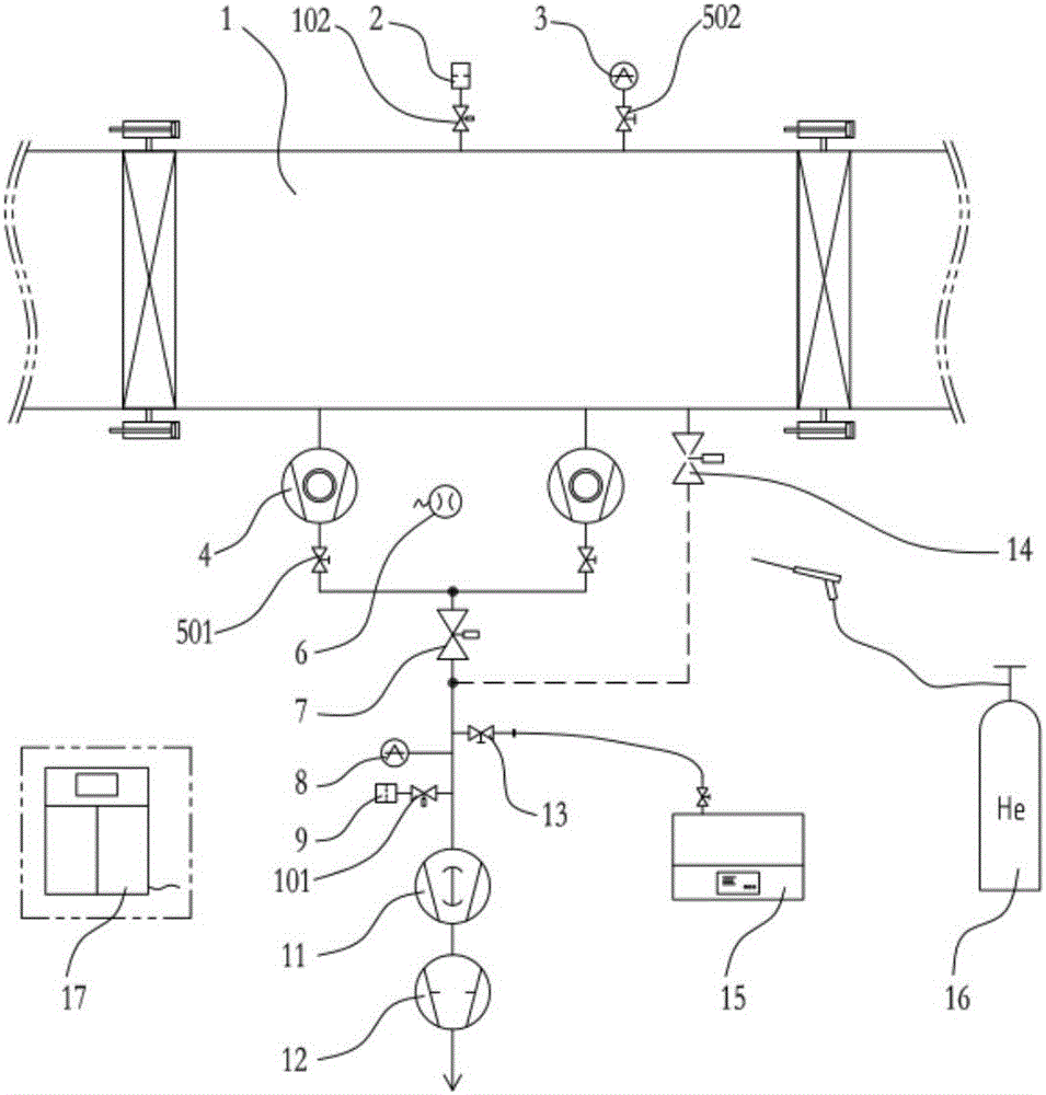
[0039]A leak detection system for a vacuum coating chamber, comprising: a vacuum chamber to be inspected 1, a leak detection device, and an electric control system. The side wall of the vacuum chamber 1 to be tested is equipped with a breaking device I2 and a vacuum detection element I3, and the leak detection device includes a high vacuum pump 4, a backing pump group I11, a backing pump group II12, a high vacuum butterfly valve I7, a vacuum detection Component II8, air breaking device II9, helium mass spectrometer leak detector 15, helium injection system 16 and electronic control system 17, the high vacuum pump 4 is directly installed on the side wall of the vacuum chamber 1 to be checked through the flange, the backing pump group I11, the backing pump group II12 are connected in series through the vacuum pipeline, and then connected in series with the high vacuum pump 4 through the high vacuum butterfly valve I7; the vacuum detection element II8 and the air breaking device I...

Embodiment 2

[0044] A leak detection system for a vacuum coating chamber, comprising: a vacuum chamber to be inspected 1, a leak detection device, and an electric control system. The side wall of the vacuum chamber 1 to be inspected is equipped with a breaking device I2 and a vacuum detecting element I3, and the leak detecting device includes a Roots pump, a rotary vane pump or a screw pump, a high vacuum butterfly valve II14, a vacuum detecting element II8, a breaking hole Device II9, helium mass spectrometer leak detector 15, helium injection system 16 and electronic control system 17, Roots pump, rotary vane pump or screw pump are connected in series through vacuum pipelines, and then connected to the vacuum chamber 1 to be tested through high vacuum butterfly valve II14; The vacuum pipeline between the high-vacuum butterfly valve II14 and the Roots pump is equipped with a vacuum detection element II8 and a void breaking device II9. On the cavity 1 and the vacuum pipeline, the pneumatic...


PUM


Abstract

The invention provides a vacuum coating cavity leak detection system and leak detection method. The system comprises a detected vacuum cavity, a leak detection apparatus, and an electric control system, the lower side of the detected vacuum cavity is connected with the leak detection apparatus, the electric control system is connected with and controls the leak detection apparatus, a sidewall of the detected vacuum cavity is provided with a vacuum breaking device I and a vacuum detection element I, the leak detection apparatus comprises high vacuum pumps, a backing pump set I, a backing pump set II, a vacuum detection element, a vacuum breaking apparatus, a helium mass spectrometer leak detector, and a helium-jetting system, the high vacuum pumps are directly arranged at the sidewall of the detected vacuum cavity through flanges, and the backing pump set I and the backing pump set II are connected in series through a vacuum pipeline and then are connected with the high vacuum pumps in series through a high vacuum butterfly valve I. According to the system and method, an automatic control system is employed, and an electrical component has the one-touch operation function; the sensitivity of leak detection is high, and leakage hole positions can be accurately located, and the size of leakage points can be judged in a quantitative manner; besides, the structure is simple, and the operation is easy.

Description

technical field [0001] The invention relates to the technical field of vacuum cavity leak detection, in particular to a vacuum coating cavity leak detection system and a leak detection method. Background technique [0002] Vacuum coating for glass modification process mainly refers to a type of glass coating that needs to be carried out under relatively high vacuum. The vacuum equipment of the coated glass production line is one of the key equipment in the coated glass production line. The high background vacuum of the coating section and the low leakage rate of the cavity are the premise and guarantee for the production of high-quality coated glass. Therefore, the processed vacuum coating chamber not only requires fast evacuation, but also requires the background vacuum to be less than 8×10 -6 mbar, cavity leak rate <1×10 -7 mbar.l / s, in order to ensure the background vacuum and leakage rate, the vacuum chamber must be welded in an airtight manner, and the quality of t...

Claims


Application Information

Patent Timeline
IPC IPC(8): G01M3/20
CPCG01M3/202
Inventor 罗松松张仰平王东张勇杰王程王翔宇
Owner TRIUMPH HEAVY IND
Why Eureka
Try Eureka