Medical flash dryer

A flash dryer and flash evaporation technology, used in non-progressive dryers, dryers, drying solid materials, etc., can solve the problem that materials are easy to accumulate at the bottom of the main machine, materials fall to the bottom of the main machine, and hot air does not enter the air. Equalize the problem to achieve the effect of improving scrap and drying efficiency, improving drying efficiency, improving effect and efficiency

Inactive Publication Date: 2017-06-09
陆文光
View PDF8 Cites 7 Cited by
  • Summary
  • Abstract
  • Description
  • Claims
  • Application Information

AI Technical Summary

Problems solved by technology

[0005] The disadvantages of the above-mentioned prior art are that, firstly, when the existing flash evaporator host is feeding, the material is easy to accumulate at the bottom of the host machine; secondly, the smashing effect of the crushing tool on the bulk material is poor; thirdly, the hot air enters the air Uneven, resulting in some materials falling to the bottom of the host, resulting in low drying efficiency

Method used


Image

  • Medical flash dryer
  • Medical flash dryer
  • Medical flash dryer

Examples


Embodiment Construction

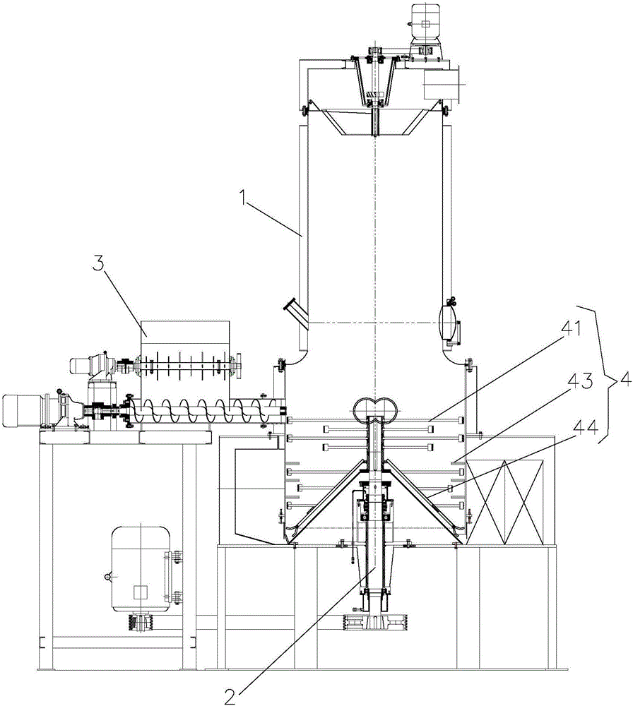
[0020] Such as Figure 1-3 , the pharmaceutical flash dryer in this embodiment includes: a flash host 1, a circular outlet is provided on the top of the flash host 1, a classifier is provided on the outlet, and the classifier includes: a movable gap Cooperate with the inverted cone cylinder on the above-mentioned discharge port, the inner wall of the inverted cone cylinder is evenly distributed with a plurality of scrap blades; each scrap blade is respectively distributed on the corresponding center vertical surface of the inverted cone cylinder; the The inverted cone cylinder is in transmission cooperation with a driving mechanism for driving the inverted cone cylinder to rotate around the central axis of the inverted cone cylinder. When working, the inverted conical cylinder rotates rapidly, so that the larger granular materials arriving there are crushed by multiple crushing blades, preventing them from falling to the bottom of the flash steamer and crushed again by the cru...


PUM


Abstract

The invention relates to a medical flash dryer. The medical flash dryer comprises a main flash evaporator and a main rotating shaft arranged at the center of the bottom of a cylindrical tower body of the main flash evaporator, wherein a conical barrel body is fixed at the middle lower part of the main rotating shaft, a gap used as an air duct is formed between the bottom edge of the conical barrel body and the inner wall of the cylindrical tower body, a plurality of movable blades are movably connected to the bottom of the conical barrel body, when the conical barrel body rotates at a certain speed, the movable blades swing outwards under the action of centrifugal force, so that the materials which pass through the gap downwards are crushed, the air duct is prevented from being blocked by the materials, and the drying efficiency of the materials is improved.

Description

technical field [0001] The invention relates to a medicinal flash drying machine with anti-sticking wall, anti-caking, anti-sinking and anti-clogging. Background technique [0002] In the flash dryer, the hot air enters the bottom of the dryer tangentially, and is driven by the agitator to form a strong rotating wind field. The material enters the dryer from the screw feeder. Under the strong action of the high-speed rotating stirring paddle, the material is dispersed under the action of impact, friction and shearing force, and the block material is quickly crushed, fully contacted with hot air, heated and dried. . The dried material is carried by the airflow into the dust collection system for collection and treatment, which meets the environmental protection requirements and the dust content is ≤50mg / m 3 The tail gas is evacuated by the induced draft fan to complete the whole drying process. [0003] The flash dryer is a new type of continuous drying equipment integrati...

Claims


Application Information

Patent Timeline
Patent Type & Authority Applications(China)
IPC IPC(8): F26B11/14F26B1/00F26B21/00F26B25/00F26B25/02F26B25/04B02C18/12B02C18/18
CPCF26B11/14B02C18/12B02C18/18F26B1/005F26B21/004F26B25/001F26B25/02F26B25/04
Inventor 陆文光张赛钢查永强顾晓峰臧德耿
Owner 陆文光
Why Eureka
Try Eureka