Laser scan range finding device

A technology of laser scanning distance measurement and laser, applied in measuring devices, optical devices, radio wave measuring systems, etc., can solve the problems of high manufacturing cost, difficulty in mass production and debugging, and high cost

Pending Publication Date: 2017-06-09
SHANGHAI SLAMTEC
View PDF4 Cites 23 Cited by
  • Summary
  • Abstract
  • Description
  • Claims
  • Application Information

AI Technical Summary

Problems solved by technology

The multi-line laser formed above generally has the following defects: 1) The laser is one of the core devices of the laser scanning rangefinder, and the market price is relatively expensive. The multi-line laser needs to be equipped with multiple lasers, and the manufacturing cost is very high; 2) Laser emission requ

Method used


Image

  • Laser scan range finding device
  • Laser scan range finding device
  • Laser scan range finding device

Examples


Embodiment Construction

[0028] In order to make the technical content disclosed in this application more detailed and complete, reference may be made to the drawings and the following various specific embodiments of the present invention, and the same symbols in the drawings represent the same or similar components. However, those skilled in the art should understand that the examples provided below are not intended to limit the scope of the present invention. In addition, the drawings are only for schematic illustration and are not drawn according to their original scale.

[0029] The specific implementation manners of various aspects of the present invention will be further described in detail below with reference to the accompanying drawings.

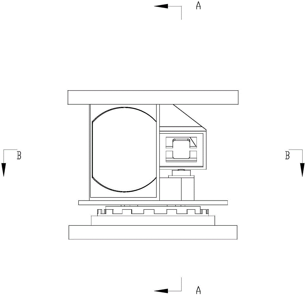
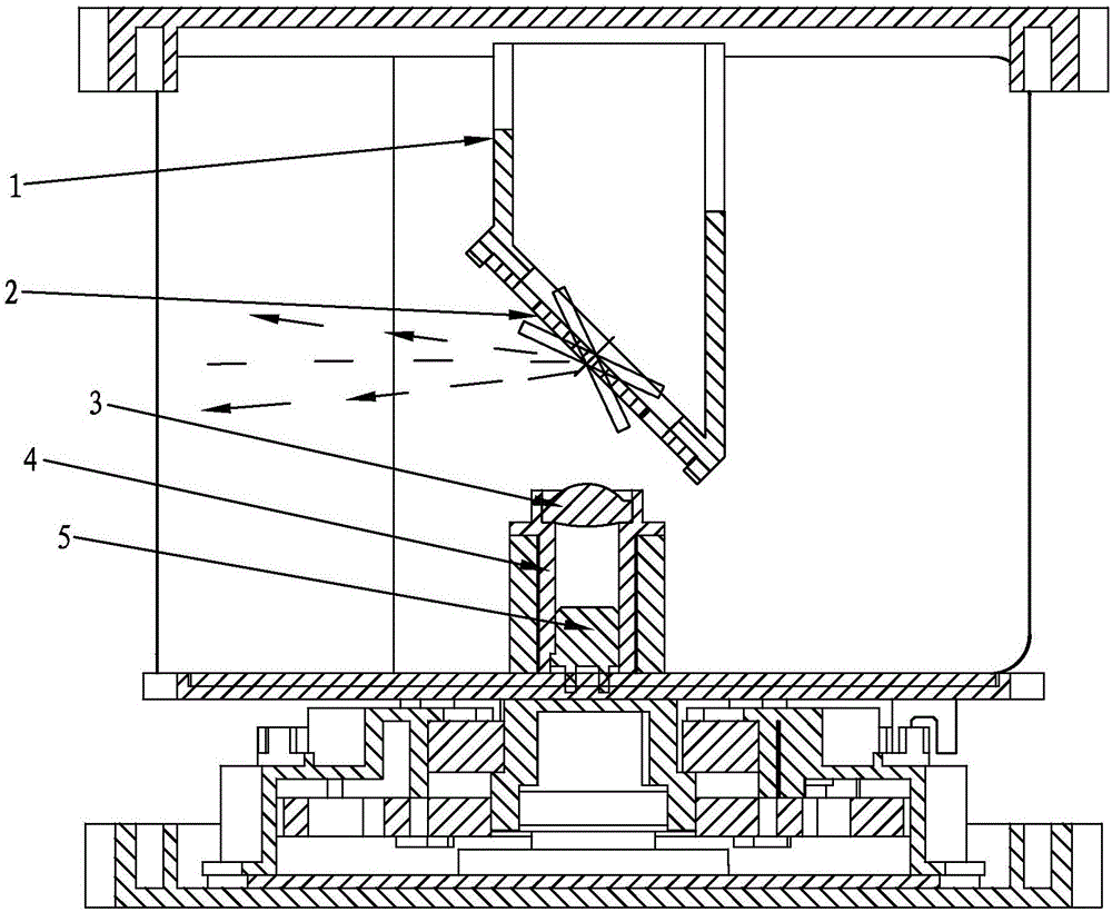
[0030] figure 1 It is a schematic diagram of the external outline of a schematic embodiment of the laser scanning ranging device of the present invention, figure 2 show figure 1 The side sectional view of the laser scanning distance measuring device cut...


PUM


Abstract

The invention provides a laser scan range finding device comprising a reflector mount, a reflector, a laser emission lens, a laser sleeve, a laser emitter, a top cover, an optical filter, a core frame, a base plate, a motor stator, a motor rotor magnetic pole, a core back plate, a laser receiver array, a receiver lens, and a receiver lens mount. The laser emission lens is used for converting the first light beam emitter by the laser emitter into a parallel light beam; the parallel light beam is reflected on the reflector surface so as to form a second light beam; when the second light beam arrives a tested target object, a third light beam is formed by the surface of the object; the third light beam is focused by the receiver lens so as to form a fourth light beam entering the laser receiver array. Compared with the prior art, the single laser emitter is combined with reflector periodical vibrations so as to realize multi-line laser emission. In addition, the angle between multi-line lasers can be controlled and adjusted through software in a microprocessor, and the angle change can be easily uniformed.

Description

technical field [0001] The invention relates to robot design technology and laser scanning technology, in particular to a laser scanning distance measuring device. Background technique [0002] Laser scanning ranging technology is a method of non-contact target object scanning and ranging using collimated beams. By rotating the collimated beam (laser) used for ranging by 360°, the distance measurement in the environment can be realized. Objects are scanned and ranging, and the contour information of the environment is extracted. [0003] In the prior art, the current multi-line laser ranging technology uses multiple laser arrays to form a laser array, and the laser array emits laser light to form a multi-line laser, which is scattered through a lens at a fixed angle. The multi-line laser formed above generally has the following defects: 1) The laser is one of the core devices of the laser scanning rangefinder, and the market price is relatively expensive. The multi-line las...

Claims


Application Information

Patent Timeline
IPC IPC(8): G01S17/10G01S7/481G01B11/02
CPCG01B11/02G01S7/481G01S17/10
Inventor 徐磁刘健刘义春陈士凯李宇翔林凌黄珏珅
Owner SHANGHAI SLAMTEC
Why Eureka
Try Eureka