Supercharge Your Innovation With Domain-Expert AI Agents!

Welding technique of compressor and liquid accumulator

A welding process and accumulator technology, applied in welding equipment, welding equipment, manufacturing tools, etc., can solve the problems of refrigerant leakage from compressors, danger of flame welding, long time consumption, etc., to ensure welding effect, welding quality, welding high quality effects

Inactive Publication Date: 2017-06-13
SANHE IND AUTOMATION EQUIP CO LTD SHUNDE DISTRICT FOSHAN CITY
View PDF7 Cites 2 Cited by
  • Summary
  • Abstract
  • Description
  • Claims
  • Application Information

AI Technical Summary

Problems solved by technology

Although the existing welding process of the main shell of the compressor and the liquid receiver is very simple, there are still the following problems: (1) With the rapid development of society, the welding efficiency of manual welding is low and time-consuming, which cannot meet the needs of modern air-conditioning manufacturers. rapid production needs
(2) Therefore, this station is very important. The quality of manual welding cannot be kept consistent. There are often welding defects such as weld penetration and incomplete welding on the metal pipe. Poor welding will cause the compressor to leak refrigerant or be scrapped. Therefore, the factory pays attention to this The staff assessment of craft production is very strict, and it needs rich experience and excellent technology to be competent for this job
(3) Due to the certain dangers and injuries associated with flame welding, there are fewer and fewer people with flame welding ability, the problem of difficulty in recruiting people in factories is very serious, and the cost of employment is getting higher and higher

Method used


Image

  • Welding technique of compressor and liquid accumulator
  • Welding technique of compressor and liquid accumulator
  • Welding technique of compressor and liquid accumulator

Examples


Embodiment 1

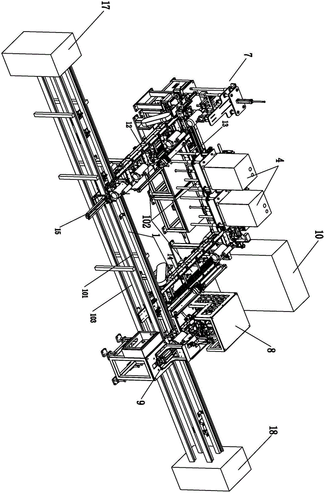
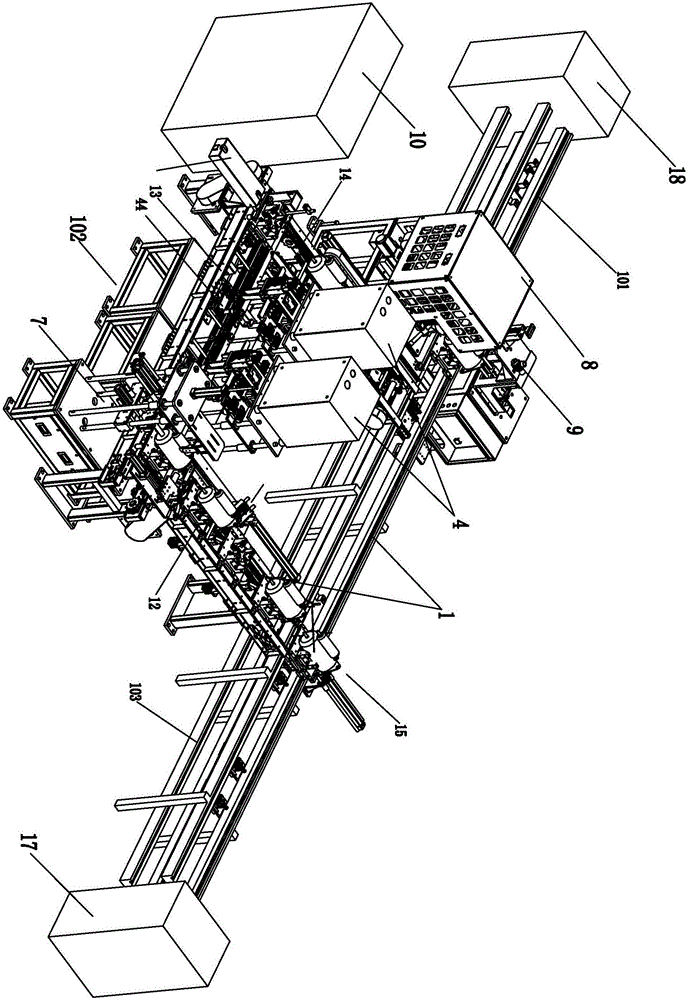
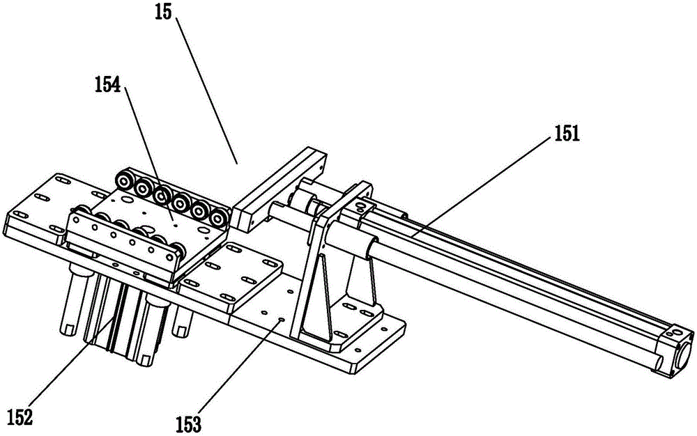
[0039] Embodiment one, see Figure 1 to Figure 19 As shown, a welding process method for a compressor and an accumulator is characterized in that it includes the following steps.

[0040] Step One: Install solder on the tube to be welded of the reservoir.

[0041] Step 2: Clean the reservoir with high-pressure air, the pressure of which is 0.1-1 MPa.

[0042] Step 3: Butt the pipe to be welded of the liquid accumulator with the pipe to be welded of the compressor, and at the same time place the liquid accumulator on the liquid accumulator bracket on the compressor for pre-fixation.

[0043] Step 4: Fill the interior of the liquid reservoir with nitrogen in advance, and the speed of nitrogen filling is 200-1000ML / S.

[0044] Step 5: Use the high-frequency brazing machine to position the liquid receiver and the compressor to ensure that the tubes to be welded of the liquid receiver and the compressor are aligned with the center of the high-frequency brazing coil. After positio...


PUM


Abstract

The invention relates to a welding process method of a compressor and a liquid accumulator. The welding technique of the compressor and the liquid accumulator includes the steps: 1, mounting solder on a pipe to be welded on the liquid accumulator; 2, using high-pressure air to wash the liquid accumulator; 3, butting the pipe to be welded on the liquid accumulator with a pipe to be welded on the compressor, and placing the liquid accumulator on a liquid accumulator support on the compressor for fixing the liquid accumulator in advance; 4, filling the interior of the liquid accumulator with nitrogen in advance; 5, using a high-frequency brazing machine to position the liquid accumulator and the compressor, and after positioning, electrifying a high-frequency brazing coil for welding, and setting welding time, current value and frequency of the high-frequency brazing machine to 6-8 S, 60-77 A and 198-208 KHZ; 6, using a positioning compaction device to position and compact the liquid accumulator and the compressor; 7, electrifying an argon welder to weld the liquid accumulator and the liquid accumulator support. The welding technique is simple in process, good in safety, high in welding efficiency, and capable of ensuring high and consistent welding quality.

Description

technical field [0001] The invention relates to the technical field of the welding process of a compressor and a liquid accumulator, in particular to a welding process method of a compressor and a liquid accumulator. Background technique [0002] Now every household is using air conditioners, the sales in the market are increasing day by day, and there are more and more manufacturers of air conditioner compressors. The main shell of the compressor and the liquid receiver are connected by pipe welding. The traditional welding process is through artificial flame brazing Filled with copper solder to achieve soldering. Although the existing welding process of the main shell of the compressor and the liquid receiver is very simple, there are still the following problems: (1) With the rapid development of society, the welding efficiency of manual welding is low and time-consuming, which cannot meet the needs of modern air-conditioning manufacturers. rapid production needs. (2) T...

Claims


Application Information

Patent Timeline
IPC IPC(8): B23K1/00B23K1/002B23K1/20B23K3/08B23K9/16B23K9/28B23K31/02
CPCB23K1/002B23K1/0008B23K1/206B23K3/087B23K9/164B23K9/28B23K31/02
Inventor 刘晖邵学彬张祺
Owner SANHE IND AUTOMATION EQUIP CO LTD SHUNDE DISTRICT FOSHAN CITY
Features
  • R&D
  • Intellectual Property
  • Life Sciences
  • Materials
  • Tech Scout
  • Unparalleled Data Quality
  • Higher Quality Content
  • 60% Fewer Hallucinations
Learn More