High-strength high-modulus low-dielectric constant fiberglass

A glass fiber and dielectric constant technology, applied in the field of high-strength, high-modulus, and low-dielectric constant glass fibers, can solve the problems of poor water resistance and low mechanical properties of glass fibers, and improve strength, modulus, and manufacturability. and the effect of moderate operability and low dielectric loss

Inactive Publication Date: 2017-06-13
王飞
View PDF0 Cites 3 Cited by
  • Summary
  • Abstract
  • Description
  • Claims
  • Application Information

AI Technical Summary

Problems solved by technology

However B 2 o 3 Too high content will directly lead to the problems of low mechanical properties of glass fiber and poor water resistance

Method used


Image

  • High-strength high-modulus low-dielectric constant fiberglass
  • High-strength high-modulus low-dielectric constant fiberglass
  • High-strength high-modulus low-dielectric constant fiberglass

Examples


Embodiment 1--14

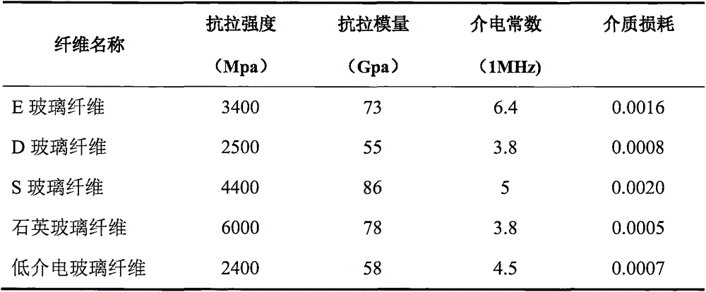
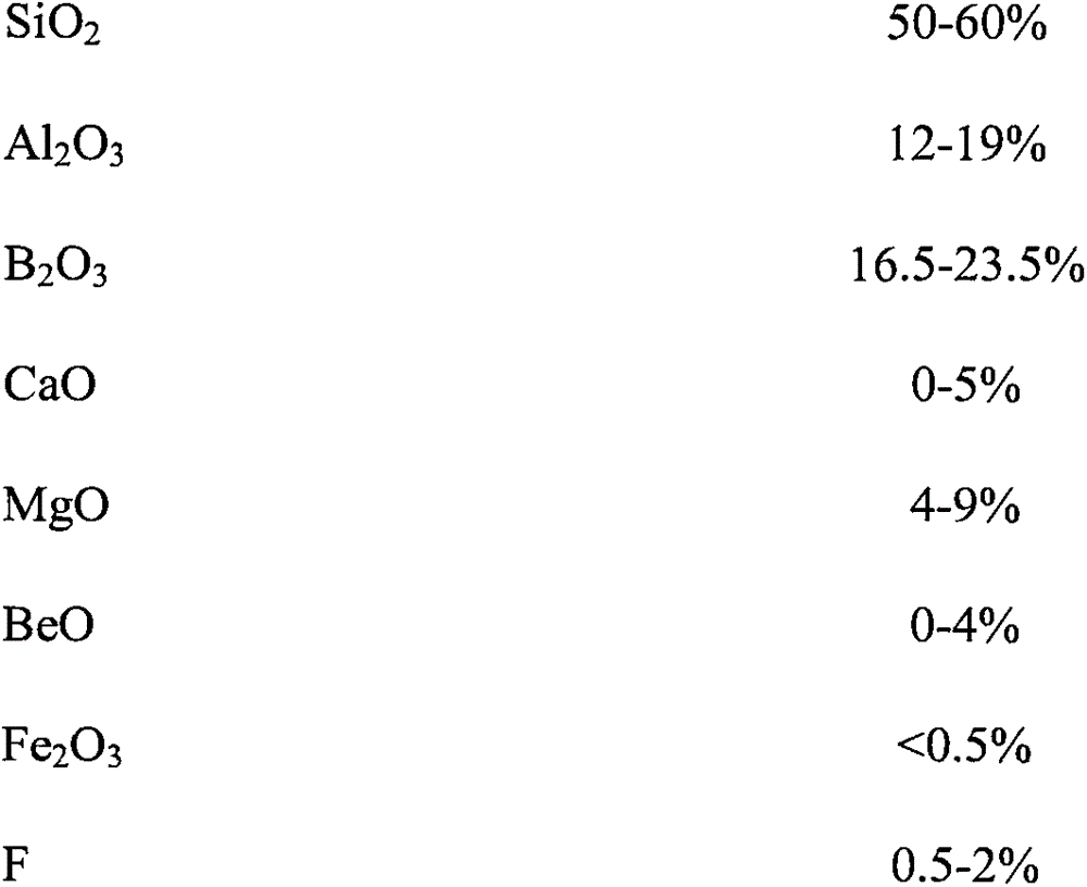
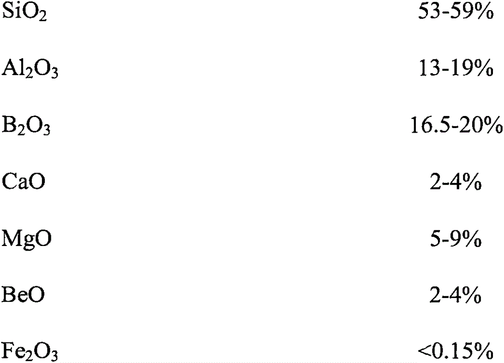
[0030] Prepare batch materials in the laboratory according to the formulas in Table (2) and Table (3), melt glass and prepare low-dielectric glass fibers, and perform performance testing (testing conditions are as remarked), and the performance is as follows:

[0031] The preparation method of each embodiment glass fiber in table (two) and table (three) is: 1) prepare according to the composition or mole percentage described in table (two) and table (three), after raw material is mixed evenly, by zirconia material and Heating to 1500-1580°C in a kiln built with chromium oxide materials to ensure that all raw materials are melted, clarified and defoamed for 24 hours, pass the clarified glass liquid through a 1000-hole platinum / rhodium alloy drain plate, and use a TL300 glass fiber drawing machine For fiber forming, the bushing temperature is adjustable at 1250-1400°C, the rotation speed of the wire drawing machine is adjustable at 2100-2800 rpm, and the diameter of the obtained ...


PUM

PropertyMeasurementUnit
dielectric lossaaaaaaaaaa

Abstract

The invention belongs to the technical field of glass fibers, in particular to a glass fiber with high strength, high modulus and low dielectric constant. The glass fibers are characterized as comprising BeO.

Description

technical field [0001] The invention belongs to the technical field of glass fibers, in particular to a glass fiber with high strength, high modulus and low dielectric constant. [0002] technical background [0003] With the development of ultra-large-scale integrated circuits (ULSI), the integration of devices is improved, and the size of components is further reduced, so that the RC interconnection delay generated by the conductive resistance R and capacitor C will increase, which limits the high-speed performance of the device. And increase energy consumption. In order to reduce impedance delay and power loss, in addition to using low-resistivity metal instead of aluminum, it is important to reduce the parasitic capacitance C brought by the dielectric layer. The capacitance C is proportional to the dielectric constant ε. Therefore, the use of low dielectric constant materials in integrated circuits (ULSI) can directly reduce the interconnection delay from the process, s...

Claims


Application Information

Patent Timeline
Patent Type & Authority Applications(China)
IPC IPC(8): C03C13/00C03B37/02H01L23/532
CPCY02P40/57C03C13/00C03B37/02H01L23/5329
Inventor 王飞
Owner 王飞
Why Eureka
Try Eureka