TDR-based anti-interference cable fault testing system and testing method

A cable fault and testing system technology, applied in the fault location, detecting faults by conductor type, and using pulse reflection method to detect faults, etc., can solve the problems of limited cable length, difficult measurement time, complex reflected wave waveform, etc. The effect of measurement accuracy, accurate measurement position, and fast and accurate echo filtering

Active Publication Date: 2017-06-13
烟台中正新技术有限公司
View PDF8 Cites 6 Cited by
  • Summary
  • Abstract
  • Description
  • Claims
  • Application Information

AI Technical Summary

Problems solved by technology

The usual method is to judge the fault point through high-speed A/D acquisition waveform. This method not only has high cost and complex circuit implementation, but also has low measurement accuracy. The first reason is that a cable may pass through during the wiring process. Multiple impedance transformation points such as connectors, hinge points, welding points, etc., when a single pulse signal is input to the cable, in addition to forming an obvious reflected pulse at the fault point (such as an open circuit or a short circuit) (in order to be consistent with the echo The difference is also called the first reflected wave), and an echo will be formed at the impedance transformation point of the cable. Although its amplitude is smaller than that of the first reflected wave, it still forms a large interference when measuring the reflection time; the second reason Yes, the first reflected wave will produce multiple reflections to form multiple echoes, and the echo amplitude is gradually attenuated, but it is also a kind of interference wave
The basic characteristic of the interference wave formed by the above two situations is that the amplitude will be smaller than the first reflected wave, but it is difficult to determine which pulse is the first reflected wave that can really represent the distance to the fault point by using the pulse time interval measurement circuit, which makes the measurement results There is uncertainty
[0003] Especially in some weak current fields with complex wiring, suc...

Method used


Image

  • TDR-based anti-interference cable fault testing system and testing method
  • TDR-based anti-interference cable fault testing system and testing method
  • TDR-based anti-interference cable fault testing system and testing method

Examples


Embodiment Construction

[0043] The principles and features of the present invention are described below in conjunction with the accompanying drawings, and the examples given are only used to explain the present invention, and are not intended to limit the scope of the present invention.

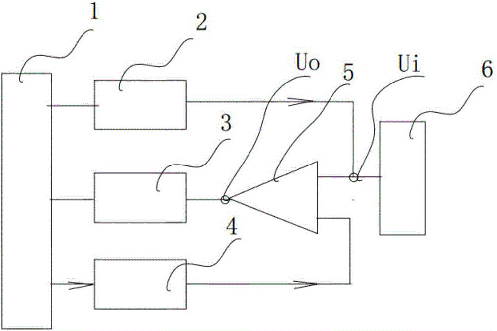
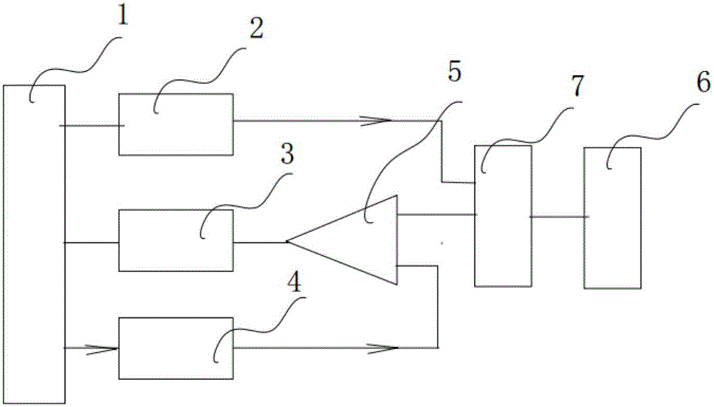
[0044] Such asfigure 1 As shown, a TDR-based anti-interference cable fault test system includes a main control module 1, a pulse generation module 2, a pulse time interval measurement module 3, a D / A converter 4 and a comparator 5; here the main control module can be SCM and other components.

[0045] The pulse generating module 2 is electrically connected with the main control module 1 and the cable under test 6; the comparator 5 includes a reference terminal, a signal input terminal and a comparison output terminal, and the digital terminal of the D / A converter 4 and The analog end is electrically connected with the reference end of the main control module 1 and the comparator 5 respectively, and the pulse time in...


PUM


Abstract

The invention relates to the technical field of cable fault testing, and particularly relates to a TDR-based anti-interference cable fault testing system. The TDR-based anti-interference cable fault testing system is characterized by comprising a master control module for controlling the system to work, a pulse generation module for sending a single pulse signal to a tested cable, a pulse time interval measurement module for measuring a pulse time interval, a D/A converter for providing comparison reference voltage and a comparator for filtering an echo. The invention further relates to a testing method. The method comprises the steps of (1) providing the comparison reference voltage to the comparator; (2) transmitting the single pulse signal to the tested cable; (3) judging whether a first reflected wave is screened out or not, if not, adjusting the comparison reference voltage and repeating the previous steps until the first reflected wave is screened out; and (5) measuring the time interval between the reflected wave and the first reflected wave and completing measurement. The testing system and the testing method have the beneficial effects that a measurement interference signal can be effectively filtered and a first reflected pulse is accurately determined, thereby quickly determining a cable fault position.

Description

technical field [0001] The invention relates to the technical field of cable fault testing, in particular to a TDR-based anti-interference cable fault testing system and a testing method using the system. Background technique [0002] The time domain reflectometry (TDR) is used to calibrate the location of the fault point by reflecting the low-voltage high-speed pulse and measuring the time difference between the transmitted pulse and the reflected pulse at the fault point. The attenuation of the reflected pulse varies with the length and material of the line. The attenuation is large, which requires signal amplification of the reflected pulse. The usual method is to use high-speed A / D acquisition waveform to realize fault point judgment. This method not only has high cost and complex circuit implementation, but also has low measurement accuracy. The first reason is that a cable may pass through Multiple impedance transformation points such as connectors, hinge points, weld...

Claims


Application Information

Patent Timeline
IPC IPC(8): G01R31/08G01R31/11
CPCG01R31/083G01R31/11Y04S10/52
Inventor 李铁赵剑峰肖楚琬应朝龙
Owner 烟台中正新技术有限公司
Why Eureka
Try Eureka