Novel rotating rectifier with fault monitoring function

A rotating rectifier and fault monitoring technology, applied in the direction of output power conversion device, AC power input conversion to DC power output, instruments, etc., can solve the problem of increasing armature current and field current of AC exciter, and easily burning out the insulation of excitation winding layer, high voltage of power supply, etc., to achieve the effects of reducing harmonics, fast transmission speed, and fewer switching devices

Inactive Publication Date: 2017-06-13
HARBIN UNIV OF SCI & TECH
View PDF5 Cites 13 Cited by
  • Summary
  • Abstract
  • Description
  • Claims
  • Application Information

AI Technical Summary

Problems solved by technology

[0003] The turn-on voltage of the traditional power supply in the rotary rectifier is relatively high. When the induction voltage of the excitation winding of the synchronous motor is already high, the rotary rectifier controller still cannot turn on the starting power module, and it is easy to burn the insulation layer of the excitation winding;
[0004] If there is an open circuit or a short circuit in a bridge arm of the rotating rectifier module, it will cause an increase in the armature current and field current of the AC exciter. If the system cannot deal with the fault immediately, it will damage the device or even burn the entire system.

Method used


Image

  • Novel rotating rectifier with fault monitoring function
  • Novel rotating rectifier with fault monitoring function
  • Novel rotating rectifier with fault monitoring function

Examples


specific Embodiment approach 1

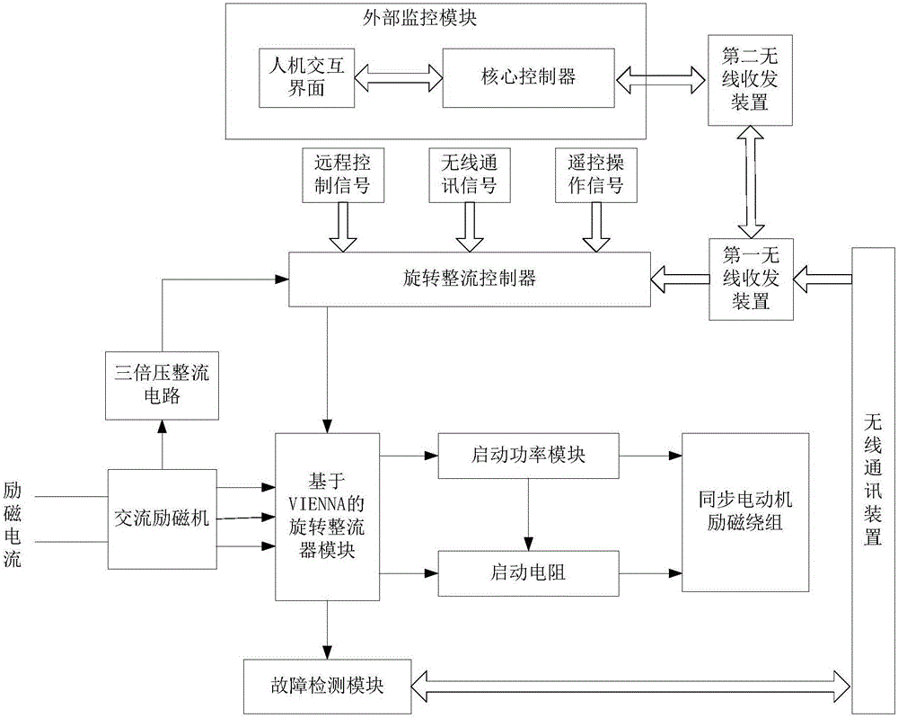
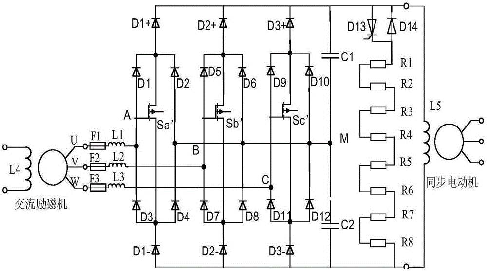
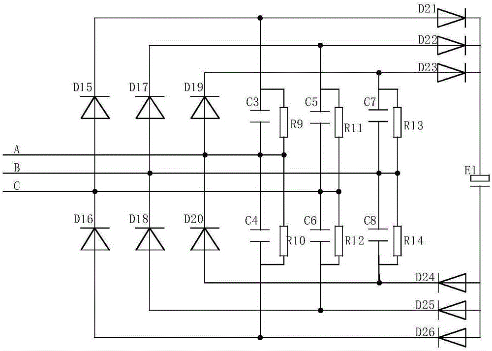
[0046] Specific implementation mode one: combine Figure 1~3Describe this embodiment, the novel rotary rectifier with fault monitoring function of this embodiment is as follows figure 1 As shown, including: AC exciter, three-phase triple voltage rectifier circuit, rotary rectifier controller, VIENNA-based rotary rectifier bridge module, starting power module, starting resistor, synchronous motor excitation unit, fault detection module, wireless communication device, A first wireless transceiver device, a second wireless transceiver device and an external monitoring module;

[0047] The input end of the AC exciter is connected to the input excitation current, the output end is connected to the VIENNA-based rotary rectifier bridge module and the input end of the three-phase triple voltage rectifier circuit, and the output end of the three-phase triple voltage rectifier circuit is connected to the rotary rectifier controller, the output end of the rotary rectification controller...

specific Embodiment approach 2

[0074] Specific implementation mode two: combination Figure 8-9 Describe this embodiment, the novel rotary rectifier with fault monitoring function of this embodiment, adopt the flow chart as Figure 9 The following method shown balances the midpoint voltage:

[0075] Step a, DC side two capacitor voltage V dc,上 and V dc,下 The reference voltage is V x,ref,DPWM,Vienna (x=a,b,c), V dc,上 and V dc,下 Will fluctuate up and down, judge V before fluctuating dc,上 increasing or decreasing trend to determine the injected zero-sequence voltage V Z direction: at V dc,上 Inject the moment to be reduced into a positive V Z (+) make V dc,上 increase, V dc,下 decrease; conversely, at V dc,上 Inject the moment to be increased into V Z (-) make V dc,上 decrease, V dc,上 Increase;

[0076] Step b. Determine the current I in the middle of the three input currents mid positive or negative, if I mid is positive, inject positive zero-sequence voltage V Z (+), if I mid is a negative valu...


PUM


Abstract

The invention provides a novel rotating rectifier with a fault monitoring function, and relates to rotating rectifying systems. The invention aims at solving the problems that an existing rectifier is low in output power of an alternating-current exciter and high in harmonic component, a rotating rectifying controller cannot be timely started and a system fault exists. The novel rotating rectifier with the fault monitoring function comprises a three-phase triple voltage rectifying circuit, an alternating-current exciter, a rotating bridge rectifier module based on VIENNA, a start power module, a start resistor, a rotating rectifying controller, a synchronous electric exciter set, a fault detection module, a wireless communication device, a first wireless transceiving device, a second wireless transceiving device and an external monitoring module. According to the novel rotating rectifier with the fault monitoring function, a neutral-point potential balance method of injecting zero-sequence voltages is adopted, zero-sequence voltages VZ(+) and VZ(-) are injected into a three-phase reference voltage at different moments, and the problem is solved that two capacitor voltages of a direct current busbar are not balanced.

Description

technical field [0001] The invention relates to a novel rotary rectifier with a fault monitoring function and relates to a rotary rectifier system. Background technique [0002] With the continuous development of electromagnetic drive technology, rotating rectifiers have been widely used in industry. Each bridge arm of the traditional rotary rectifier uses a thyristor and a diode in series. The connection of this structure increases the harmonics on the AC exciter side and reduces the power factor, which restricts the development of the rotary rectifier; [0003] The turn-on voltage of the traditional power supply in the rotary rectifier is relatively high. When the induction voltage of the excitation winding of the synchronous motor is already high, the rotary rectifier controller still cannot turn on the starting power module, and it is easy to burn the insulation layer of the excitation winding; [0004] If there is an open circuit or short circuit in a bridge arm of the...

Claims


Application Information

Patent Timeline
Patent Type & Authority Applications(China)
IPC IPC(8): H02M7/155H02M1/12H02M1/42H02P6/20H02P21/34G01R31/00G01R19/25
CPCG01R19/25G01R31/00H02M1/12H02M1/4208H02M7/155H02P6/20Y02B70/10
Inventor 高晗璎孙守旭
Owner HARBIN UNIV OF SCI & TECH
Why Eureka
Try Eureka