IGBT drive circuit

A drive circuit, INV1 technology, applied in the direction of electrical components, electronic switches, pulse technology, etc., can solve the problem of long tail of current, solve the problem of surge voltage, reduce switching loss, and improve the effect of overshoot voltage

Inactive Publication Date: 2017-06-13
UNIV OF ELECTRONICS SCI & TECH OF CHINA
View PDF5 Cites 10 Cited by
  • Summary
  • Abstract
  • Description
  • Claims
  • Application Information

AI Technical Summary

Problems solved by technology

[0005] What the present invention aims to solve is to propose an IGBT drive circuit in combination with the characteristics of the IGBT device, which adopts variable slope driving in the turn-off phase, and solves the long current tail during the turn-off period without the need for an additional RC passive absorption network. And the problem of surge voltage generated, while improving the circuit anti-dv / dt and di / dt characteristics, reducing the overshoot voltage during the turn-off process and improving the overall electromagnetic interference characteristics

Method used


Image

  • IGBT drive circuit
  • IGBT drive circuit
  • IGBT drive circuit

Examples


Embodiment Construction

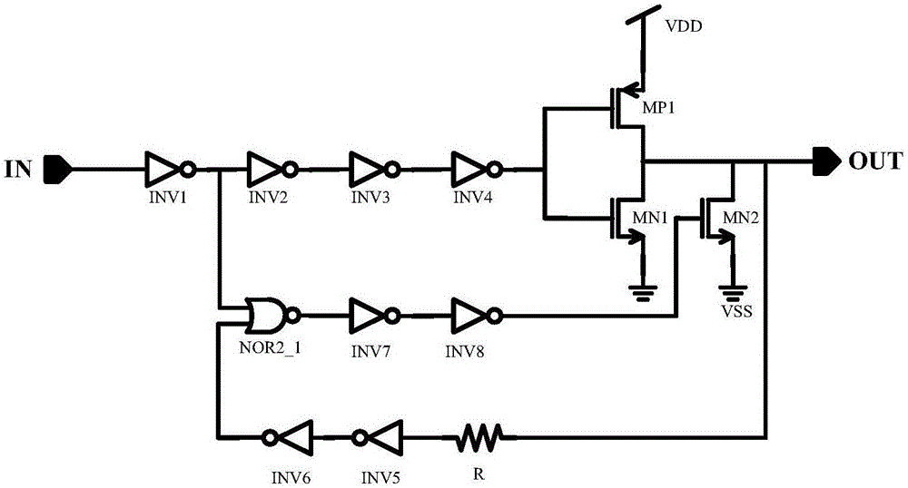
[0020] The present invention adopts the variable slope driving method, such as figure 1 Shown is an implementation form of the present invention, including a first inverter INV1, a second inverter INV2, a third inverter INV3, a fourth inverter INV4, a fifth inverter INV5, a sixth inverter Inverter INV6, seventh inverter INV7, eighth inverter INV8, PMOS transistor MP1, first NMOS transistor MN1, second NMOS transistor MN2, resistor R, two-input NAND gate NOR2_1, first inverter INV1 The input terminal of the input terminal is connected to the input signal IN, and the output terminal thereof is connected to the input terminal of the second inverter INV2 and the first input terminal of the two-input NOR gate NOR2_1; the input terminal of the third inverter INV3 is connected to the second inverter INV2 the output terminal of the fourth inverter INV4, the output terminal of which is connected to the input terminal of the fourth inverter INV4; the gates of the PMOS transistor MP1 and...


PUM


Abstract

The invention discloses an IGBT drive circuit and belongs to the technical field of an electronic circuit. In a switch-off phase, variable-slope drive is employed; a switch-off process is divided into two phases through special size design of a resistor R and a fifth inverter INV5; in the T2 to T3 phase, only a first NMOS transistor MN1 is switched on, and the circuit is in a slow discharge state, so overshoot voltage is improved and the surge voltage problem occurring in a switch-off period is solved; and in the T3 to T4 phase, a second NMOS transistor MN2 is switched on after delay time designed through the resistor R and the fifth inverter INV5, the circuit enters a fast discharge state, the switch-off process of the whole IGBT is accelerated, switch losses is reduced, a discharge current is increased, and the trailing time is greatly reduced. According to the circuit, an extra RC passive absorption network is unnecessary; the damping losses resulting from a traditional RC absorbing circuit are avoided; the pull-down capability of the drive circuit of the switch-off process is ensured; a resistance value in the latter stage is relatively low, so the circuit is high in dv / dt resistance; and the electromagnetic interference property of the integrated circuit is improved.

Description

technical field [0001] The invention belongs to the technical field of electronic circuits, and in particular relates to a drive circuit suitable for IGBT proposed by combining the characteristics of IGBT devices. Background technique [0002] IGBT gate drive integrated circuit is one of the typical circuits of HVIC (high voltage integrated circuit). Due to its high reliability, small area and high effect, it is widely used in household appliances and industrial equipment, aviation, aerospace, weapon systems, etc. An important part of HVIC is the driving control of IGBT, but unreasonable driving will produce high dv / dt and di / dt, and high dv / dt and di / dt switching drive poses a great challenge to the reliability of IGBT , can easily lead to damage to the IGBT. [0003] The main reason for IGBT performance attenuation or even damage is that the IGBT turn-off mechanism and the change law of voltage and current during the turn-off process are unclear, which leads to the inabil...

Claims


Application Information

Patent Timeline
Patent Type & Authority Applications(China)
IPC IPC(8): H03K17/567
CPCH03K17/567
Inventor 周泽坤王彦龙石跃王卓张波
Owner UNIV OF ELECTRONICS SCI & TECH OF CHINA
Why Eureka
Try Eureka