Self-power supply method for train

A self-powered, train technology, applied in the field of electronics, can solve problems such as inability to meet the requirements of train electrical equipment, limited battery capacity, and solar cells affected by climate and operating hours.

Active Publication Date: 2017-06-20
NANCHANG INST OF TECH
View PDF17 Cites 3 Cited by
  • Summary
  • Abstract
  • Description
  • Claims
  • Application Information

AI Technical Summary

Problems solved by technology

The way of installing battery power supply is easy to operate and the power supply quality is good, but due to the limited capacity of the battery, it cannot provide a safe and reliable power supply for a long time; the solar battery is affected by the climate and operating time, and cannot provide a safe and reliable power supply for a long time; the compressed air power generation device is used The compressed air power generation of the pneumatic brake system of the train, because the work of the pneumatic brake system is intermittent and the intermittent time is uncertain, this will cause the power generation to fail to meet the needs of the train's electrical equipment; vibration power generation technology is limited by piezoelectric materials, and The output power is too low to meet the needs of train electrical equipment; harsh operating conditions limit the use of wind power generation devices on trains; pulley drive shaft end power generation devices, shaft end disc permanent magnet Both the device and the bearing power generation device use the mechanical energy of the train axle rotation to convert it into electrical energy. Their common feature is that the power generation is determined by the rotational speed of the axle shaft. Continuous power generation can be realized during the running of the train and can provide sufficient power for electrical equipment.

Method used


Image

  • Self-power supply method for train
  • Self-power supply method for train
  • Self-power supply method for train

Examples


Embodiment 1

[0070] Embodiment 1: A kind of self-power supply method for train, carries out power supply control based on train self-power supply system;

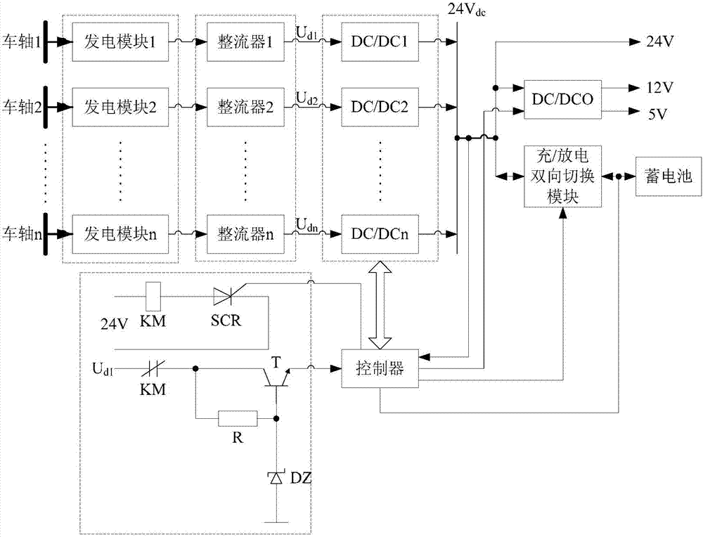
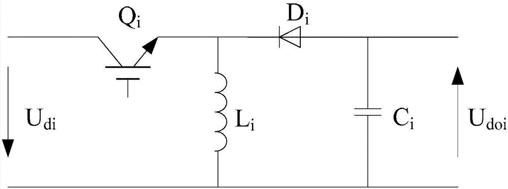
[0071] The train self-power supply system includes a controller, a storage battery, and at least one self-generated power supply branch; each self-generated power supply branch includes a power generation module, a rectifier and a DC / DC conversion unit connected in series; the power generation module is connected to the axle, and the The drive of the axle produces alternating current;

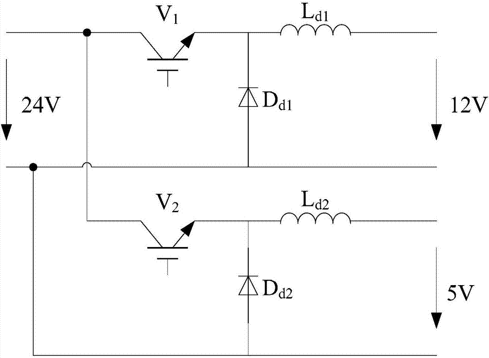
[0072] Both the output end of the DC / DC conversion unit and the storage battery are connected to the DC bus;

[0073] The DC bus supplies power to the controller;

[0074] The DC / DC conversion unit is controlled by the controller;

[0075] There are 3 power supply lines for the controller:

[0076] (1) Powered by DC bus;

[0077] (2) Powered by batteries;

[0078] (3) The controller starts the power supply control circuit to supply power;

[0079] ...


PUM


Abstract

The invention discloses a self-power supply method for a train. The self-power supply method for the train comprises the steps of step 1, enabling a storage battery to provide working power supply to a controller at the starting moment of the train; and if the controller detects that the voltage of the storage battery is lower than a first preset value (such as 20V), turning to step 2; and if the controller detects an output voltage of a direct current bus reaches a second preset value (such as 24V), turning to step 3; step 2, enabling the controller to start a power supply unit to supply power to the controller; if the controller detects that the output voltage of the direct current bus reaches the second preset value (such as 24V), enabling the controller to transmit a high level signal or pulse to a triggering end of a silicon controlled rectifier (SCR); enabling a contactor KM to act; disconnecting a power supply branch circuit of Ud1; and turning to step 3; and step 3, enabling the direct current bus to provide direct current power supply to the controller. The self-power supply method for the train is easy to implement and can supply power to load of the train without an external power supply.

Description

technical field [0001] The invention belongs to the field of electronic technology and relates to a self-power supply method for trains. Background technique [0002] With the development of the market economy, the transportation of railways, highways, waterways, and aviation is developing day by day, and the competition in the four major transportation fields is becoming more and more fierce. Railway freight has been challenged unprecedentedly. Requirements, on-board dynamic safety monitoring equipment for railway trains, electronic anti-skid devices, etc. were proposed. However, for a long time, due to the continuous dismantling and marshalling of railway trains, the electric energy on the locomotives cannot be effectively transmitted to each train, so other carriages and bogies generally have no power supply except the locomotives. Electrical equipment such as monitoring equipment, electronic anti-skid devices, communication equipment, and lighting are inconvenient to us...

Claims


Application Information

Patent Timeline
Patent Type & Authority Applications(China)
IPC IPC(8): B60L1/00B61D43/00H02J7/14
CPCH02J7/14B61D43/00B60L1/00B60L2210/14B60L2200/26B60L2210/12Y02T30/00
Inventor 王翠欧阳俊铭张兴旺曾瑄朱能飞
Owner NANCHANG INST OF TECH
Why Eureka
Try Eureka