Flywheel catapult
A catapult and flywheel technology, applied in the field of flywheel catapult, can solve the problems of high use cost, high manufacturing cost of steam catapult and electromagnetic catapult, and achieve the effects of low manufacturing cost, shortening of catapult cycle time and volume reduction.
- Summary
- Abstract
- Description
- Claims
- Application Information
AI Technical Summary
Problems solved by technology
Method used
Image
Examples
Embodiment 1
[0063] Flywheel catapult for military carrier aircraft
[0064] 1. The working process of the shipboard flywheel catapult
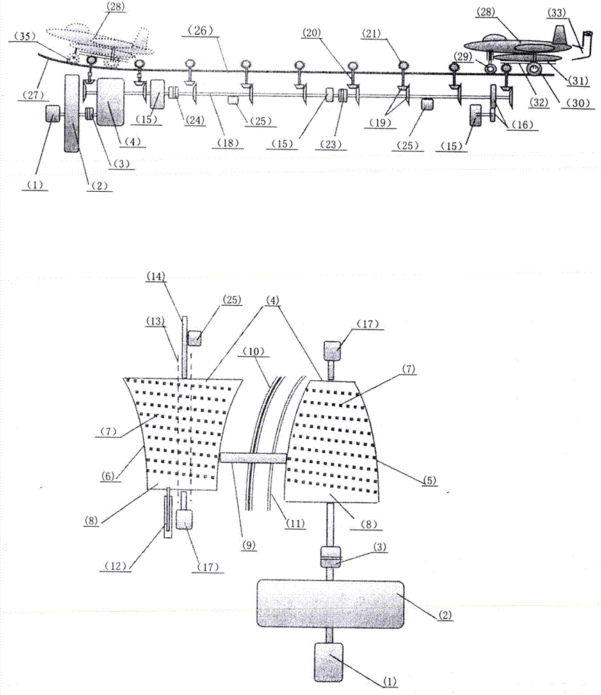
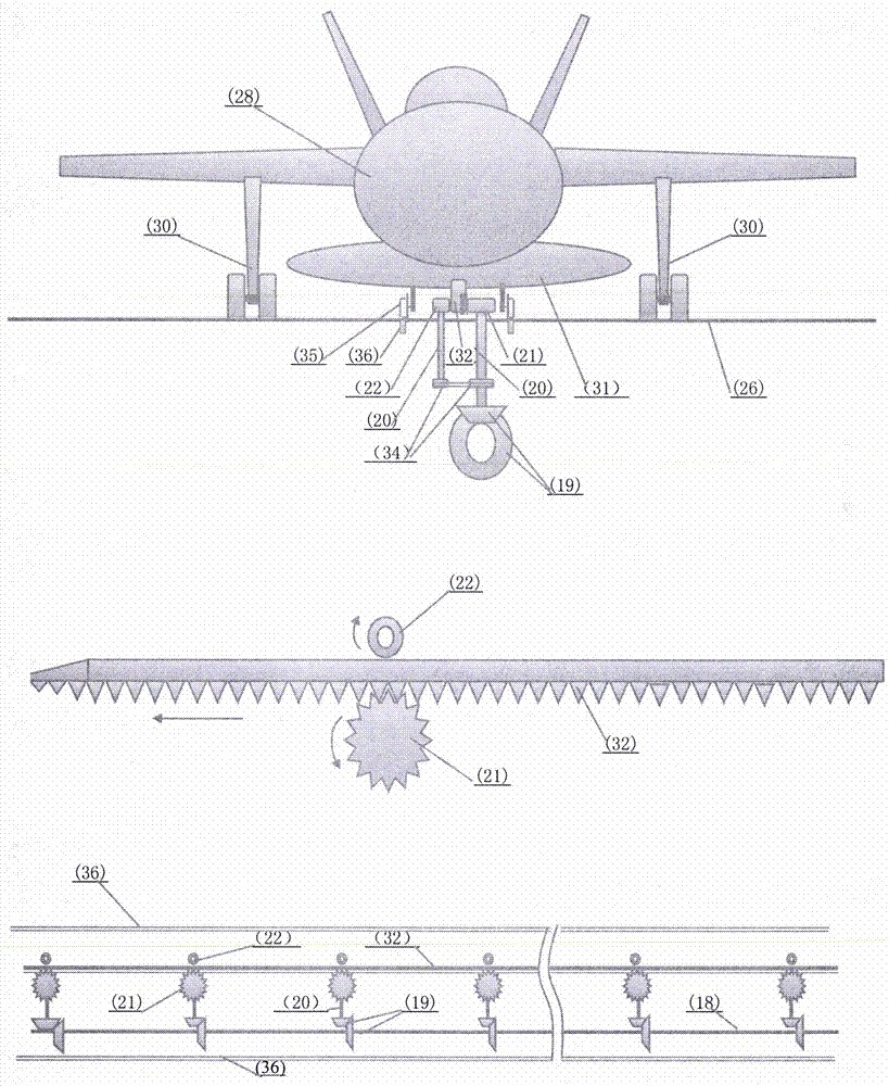
[0065] in the attached figure 1 , 2 , 3, 4, and 9:
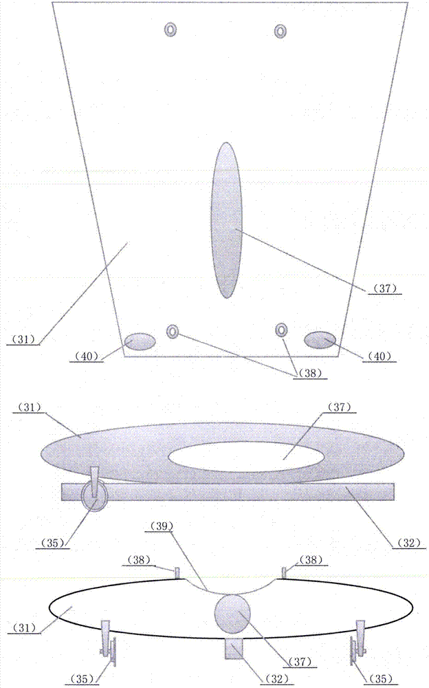
[0066] When the aircraft (28) was in place, the wheels of the front landing gear (29) drove into the wheel grooves at the place, so that the fuselage was lowered, so that the guide wheels (35) were just in place on the ejection guide rail (36), Aircraft moves forward again, allows airborne rack (32) to mesh with drive gear (21), retracts nose landing gear then, allows the weight that nose landing gear bears to be pressed on guide wheel (35) fully.
[0067] 2. After the aircraft is successfully ignited, start the booster motor (15), mainly using the energy provided by the booster motor, plus the thrust of the aircraft engine and the friction of the differential coupling (3), the three forces work together to push the aircraft to start .
[0068] 3. When the rotational speed of the driving wheel (5) ...
Embodiment 2
[0295] Land Airport Flywheel Catapult
[0296] 1. Working process of land airport catapult
[0297] in the attached Figure 5 , 6 middle:
[0298] 1. The land airport has a relatively generous location and can provide a long-distance brake slideway (56). It is proposed to use the winches (51, 52)-steel cables (53) as the power to pull the traction shuttle (54), The transmission mechanism can be simplified and the weight can be reduced.
[0299] 2. Land airport catapults are suitable for ejecting military aircraft and civil aviation aircraft, and the take-off runway and landing runway should be set separately.
[0300] 3. Ordinary airports are equipped with single-power small and medium-sized catapults, which can eject aircrafts below 90 tons. Large-scale airports are equipped with dual-power large-scale catapults, equipped with 1 to 2 sets of medium-sized winches and 1 set of large winches, which can eject two aircrafts below 90 tons at the same time; the combination of t...
Embodiment 3
[0435] Operation Rocket Flywheel Catapult
[0436] 1. The working process of the rocket catapult
[0437] in the attached Figure 7 middle:
[0438] 1. The rocket catapult is equipped with 4 sets of power systems (2, 68, 69, 70). It is planned to activate the number of power systems according to the thrust requirements.
[0439] 2. Set the final rotational speed of the flywheel (2) according to the required final ejection velocity.
[0440] 3. According to the diameter of the rocket (67), adjust the length of the telescopic branch transmission shaft (74) of the launching frame, so that the drive gear (21) and the hedge drive gear (76) are meshed with the rocket rack (73). Let the guide slide rod (77) embed in the guide chute (78).
[0441] 4. The rocket (67) is in place, and the launcher receives a take-off command, and after the rocket is successfully ignited, the ejection system is started.
[0442] 5. The rocket rack (73) arrives at the set position, the travel switch ...
PUM
| Property | Measurement | Unit |
|---|---|---|
| Length | aaaaa | aaaaa |
| Width | aaaaa | aaaaa |
| Diameter | aaaaa | aaaaa |
Abstract
Description
Claims
Application Information
 - R&D Engineer
- R&D Manager
- IP Professional
- Industry Leading Data Capabilities
- Powerful AI technology
- Patent DNA Extraction
Browse by: Latest US Patents, China's latest patents, Technical Efficacy Thesaurus, Application Domain, Technology Topic, Popular Technical Reports.
© 2024 PatSnap. All rights reserved.Legal|Privacy policy|Modern Slavery Act Transparency Statement|Sitemap|About US| Contact US: help@patsnap.com


