Device for testing unfolding of missile wings under multi-angle high-speed rotation condition of missile body

A high-speed rotation, multi-angle technology, applied in the direction of ammunition testing, ammunition, weapon accessories, etc., can solve the problem of difficulty in identification and testing, and achieve the effect of safe and reliable working environment, elimination of rotational speed loss, and easy maintenance.

Inactive Publication Date: 2017-06-20
BEIJING INSTITUTE OF TECHNOLOGYGY
View PDF6 Cites 2 Cited by
  • Summary
  • Abstract
  • Description
  • Claims
  • Application Information

AI Technical Summary

Problems solved by technology

[0003] There are often pin holes and fixed pins designed to lock and expand the wings at the root of the wing and the body, and the movement of the pin at the tail of the body is a small displacement in a narrow space, which is difficult to identify and test. Therefore, it cannot be directly characterized whether the pin is reliably fixed under the existing means, and the conduction and amplification of small displacements have become a means of characterization

Method used


Image

  • Device for testing unfolding of missile wings under multi-angle high-speed rotation condition of missile body
  • Device for testing unfolding of missile wings under multi-angle high-speed rotation condition of missile body
  • Device for testing unfolding of missile wings under multi-angle high-speed rotation condition of missile body

Examples


Embodiment 1

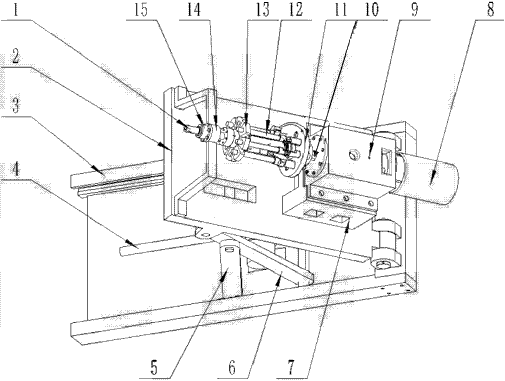
[0037] A rotary table used for the elastic wing locking test under the condition of multi-angle high-speed rotation of the projectile, which is composed of a shaft rotating part, a platform lifting part and a device for testing the deployment of the wing.

[0038] The rotating part of the shaft system includes: hollow shaft 1, variable frequency motor 8, motor seat 9, transmission shaft 10, first chuck 11, bracket 12, second chuck 13, bearing seat 14, first multi-way slip ring 15, cone Roller bearing 16, second multiple slip ring 17, electromagnetic clutch 18;

[0039] The rotating part of the shaft system is powered by the variable frequency motor 8. The variable frequency motor shaft and the transmission shaft 10 are connected by an electromagnetic clutch 18, and the start and stop of the entire rotating system are controlled by controlling the electromagnetic clutch. Two tapered roller bearings are placed on the shoulder of the solid shaft to bear the axial force, and 4 grooves ...


PUM


Abstract

The invention relates to a device for testing unfolding of missile wings under a multi-angle high-speed rotation condition of a missile body, in particular to research on the rotating characteristic of the missile body under different angles, and belongs to the field of experimental research design of a high-speed rotating platform. The device comprises a probe, a transmission rod, a pre-tightening spring, a straight sliding type potentiometer, a voltage acquirer, a fixed-value resistance, a power source, a shell, a shell cover and a limiting bolt. The angle and the rotating speed of the missile body in a flying state are simulated through the rotating table, and the device, for testing unfolding of the missile wings, installed in the rotating table represents whether the missile wings are completely unfolded and locked by conducting, amplifying and detecting the displacement of a fixing pin. The two ends of the missile body are fixed to be connected with a support through the rotating table, and it is guaranteed that the missile body can stably rotate under a high rotating speed. The straight sliding type potentiometer is adopted for the testing device, a displacement signal of the pin is linearly converted into an electric signal, and the testing result can better perform representation and display.

Description

Technical field [0001] The invention relates to a device for testing the deployment of a projectile wing under the condition of a multi-angle high-speed rotation of a projectile, in particular to the study of the characteristics of the projectile body at different angles, and belongs to the field of experimental research and design of a high-speed rotating platform. Background technique [0002] Rotating missiles are small missiles with simple systems, low cost, and high reliability. This type of missile was first adopted by most anti-tank missiles. With the development of missiles, especially tactical missiles, in the direction of miniaturization, automation, autonomy, and ammunition, many small air defense missiles, especially portable missiles, have gradually adopted rotating bombs. The tail wings of most rotating missiles are before launching. It is closed inside the projectile body, and only after receiving the trigger signal, the inner ejection device unfolds the projectile...

Claims


Application Information

Patent Timeline
Patent Type & Authority Applications(China)
IPC IPC(8): F42B35/02
CPCF42B35/02
Inventor 武志文刘旺刘玉群王燕宾
Owner BEIJING INSTITUTE OF TECHNOLOGYGY
Why Eureka
Try Eureka