Infrared imaging-based on-line dynamic automatic laying defect detection apparatus and infrared imaging-based on-line dynamic automatic laying defect detection method

An infrared imaging and dynamic detection technology, used in material defect testing and other directions, can solve the problems of polluted composite material layup, inability to identify and analyze, and insensitive to layered defects, so as to improve laying, improve quantitative analysis accuracy and save money. The effect of rework time

Inactive Publication Date: 2017-06-20
NANJING UNIV OF AERONAUTICS & ASTRONAUTICS
View PDF5 Cites 8 Cited by
  • Summary
  • Abstract
  • Description
  • Claims
  • Application Information

AI Technical Summary

Problems solved by technology

Since such defects exist inside the prepreg tape layup, they cannot be effectively identified and analyzed visually, so it is necessary to use non-destructive testing to identify and detect
[0005] At present, the non-destructive testing methods suitable for composite material defects mainly include ultrasonic C-scan and X-ray inspection, etc. Among them, ultrasonic C-scan must use medium, such as water, which will pollute the composite material layup, while the ultrasonic C-scan technology of air medium has great influence on signal processing. The technical requirements are relatively high, and the signal-to-noise ratio of the air-coupled ultrasonic signal is improved; X-ray inspection is mainly suitable for detecting defects such as changes in material thickness or density of 1%-2%, but it is not sensitive to delamination defects, and the safety requirements are relatively high. Therefore, there is an urgent need for a method that can quickly and accurately identify defects and does not require high signal processing technology to detect automatic placement defects

Method used


Image

  • Infrared imaging-based on-line dynamic automatic laying defect detection apparatus and infrared imaging-based on-line dynamic automatic laying defect detection method
  • Infrared imaging-based on-line dynamic automatic laying defect detection apparatus and infrared imaging-based on-line dynamic automatic laying defect detection method

Examples


Embodiment Construction

[0025] The following is based on figure 1 and figure 2 The specific embodiment of the present invention is further described:

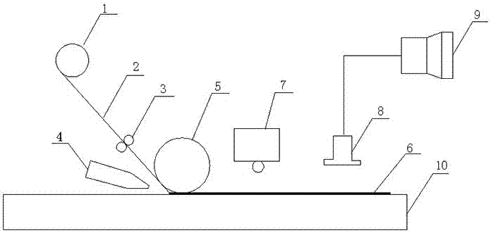
[0026] see figure 1 , an automatic placement defect online dynamic detection device based on infrared imaging, including a placement device and a defect detection device, the placement device includes a material tray 1, a feeding roller 3, a placement pressure roller 5, a hot air pipe 4 and Lay the mold 10, the defect detection device includes an infrared heat source 7, an infrared thermal imager 8 and an image processing system 9, a prepreg tape 2 is arranged on the tray 1, and the prepreg tape 2 is sequentially connected with the feed roller 3 , the laying pressure roller 5 and the laying mold 10 are connected in transmission, the infrared heat source 7 is arranged above the laying mold 10, the infrared thermal imager 8 is arranged above the laying mold 10, and the The infrared camera 8 is connected with the image processing system 9 .

[0027]...


PUM


Abstract

The invention discloses an infrared imaging-based on-line dynamic automatic laying defect detection apparatus and an infrared imaging-based on-line dynamic automatic laying defect detection method. The infrared imaging-based on-line dynamic automatic laying defect detection apparatus comprises a laying unit and a defect detection unit, the laying unit comprises a spool, feed rollers, a laying press roller, a hot blast tube, and a laying die, the defect detection unit comprises an infrared heat source, an infrared thermal imager, and an image processing system, a prepreg tape is arranged on the spool, the prepreg tape is sequentially transmissively connected to the feed rollers, the laying press roller and the laying die, the infrared heat source is arranged over the laying die, the infrared thermal imager is arranged over the laying die, and the infrared thermal imager is connected to the image processing system. The invention can implement the rapid and accurate detection of laying defects, has high capability in identifying typical laying defects, and can implement the quantitative analysis of defect dimensions.

Description

technical field [0001] The invention belongs to the field of automatic molding of composite materials, and in particular relates to an infrared imaging-based automatic placement defect online dynamic detection device and method. Background technique [0002] The automatic placement of composite materials is to bond anisotropic viscoelastic prepregs with a certain stiffness according to the specific fiber topology requirements, under the action of external fields such as heat and force, and attach them to the surface of the mold to form composite material prefabricated parts. The manufacturing process has the advantages of high efficiency, high quality, high reliability, high material utilization, and low cost. It is especially suitable for the manufacture of large-scale and complex components, reducing the number of assembled parts, saving manufacturing and assembly costs, and extremely The scrap rate and manufacturing man-hours of components are greatly reduced. [0003] H...

Claims


Application Information

Patent Timeline
Patent Type & Authority Applications(China)
IPC IPC(8): G01N25/72
CPCG01N25/72
Inventor 还大军李勇褚奇奕肖军齐俊伟
Owner NANJING UNIV OF AERONAUTICS & ASTRONAUTICS
Why Eureka
Try Eureka