

Ship-borne electronic equipment test diagnosis equipment
A technology of electronic equipment and diagnostic equipment, applied in the field of testing, can solve problems such as equipment reliability decline, difficult fault detection and integrity testing, hardware cost increase, etc., to achieve the effect of improving utilization rate and saving maintenance and guarantee funds
- Summary
- Abstract
- Description
- Claims
- Application Information
AI Technical Summary
Problems solved by technology
Method used
Image

Examples
Embodiment 1
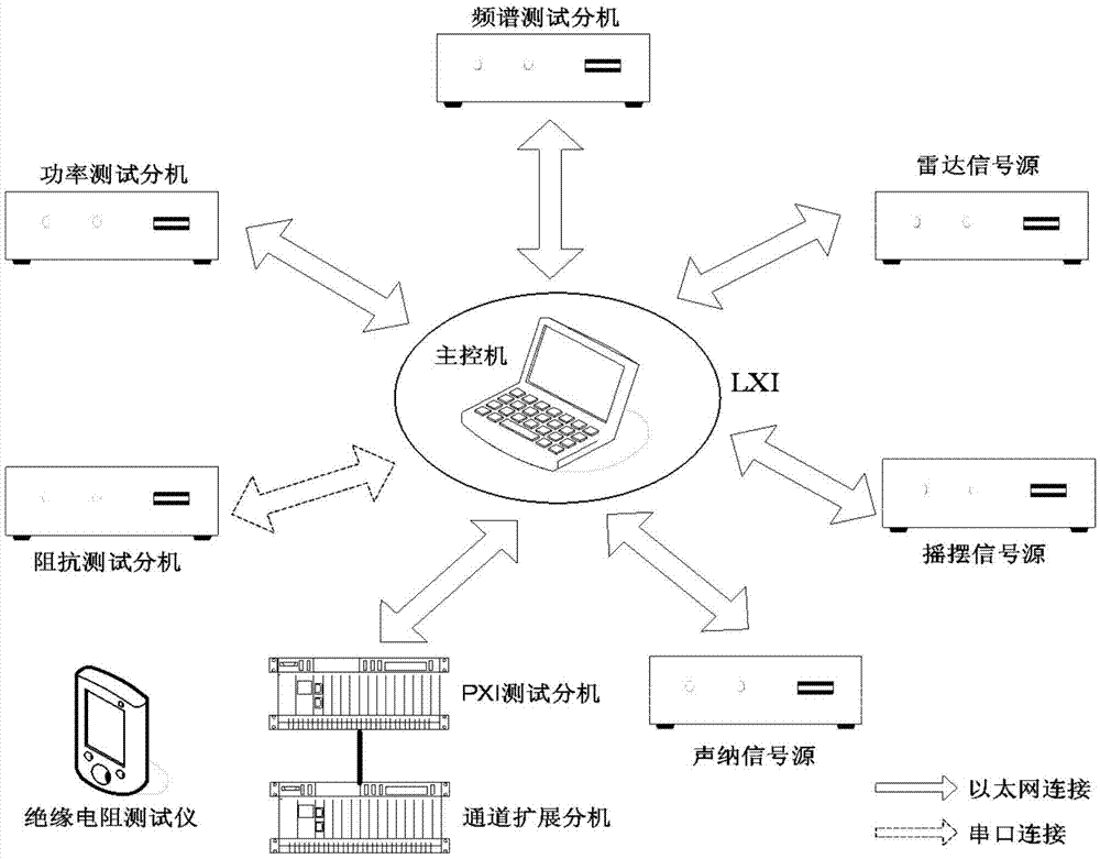
[0072] The invention can test the main functional performance index of the radar sonar, and carry out fault diagnosis and auxiliary maintenance. The main test indicators of radar include main trigger pulse test, clock reference signal test, transmitter output RF signal test, transmitter second and third level high voltage power supply test, receiver microwave signal test, intermediate frequency signal test, frequency synthesizer local oscillator signal test, Target building test, noise figure test, stable platform swing error test, etc. The main test indicators of sonar include sonar front-end amplitude consistency test, front-end phase consistency test, front-end frequency test, center frequency test of transmitting signal source, pulse width test of transmitting signal source, transmitting power amplifier test, array element testing, signal processing performance testing, etc. Several typical test methods are described below.
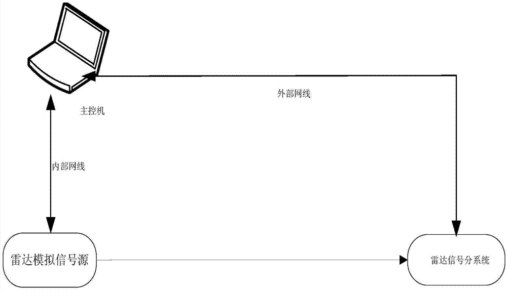
[0073] The radar target building test is main...
Embodiment 2
[0076] The uniformity of radar antenna rotation speed is an important index to judge the stability of radar servo system. The invention controls the PXI test extension by the main control computer to collect the true north signal of the servo system and calculate the uniformity index of the radar antenna rotation speed. After connecting the main control computer and the PXI test extension, set the antenna speed to N0, the main control computer controls the multi-channel test data acquisition module of the PXI test extension to read 10 true north pulse signals, and count from the first pulse, the time is T. Calculate the antenna rotational speed non-uniformity.
[0077] Antenna speed uniformity = [1-600 / (T×N0)]×100%
[0078] After the calculated result is compared with the standard index, the test conclusion is drawn.
Embodiment 3
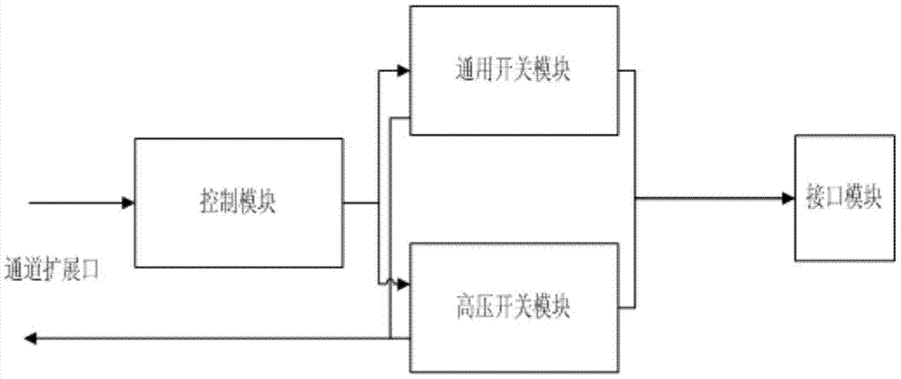
[0080] The sonar pre-consistency index has a great influence on the quality of sonar receiving and transmitting signals. The general test and diagnostic equipment can test the sonar pre-consistency through the main control computer, sonar signal source, PXI test extension, and channel expansion extension. The main control computer controls the sonar analog signal source to output standard multi-channel excitation signals and injects them from the top of the sonar front module; at the same time, it controls the PXI test extension and channel expansion extension to collect from the signal output of the front module, and the test extension will collect The original data is returned to the main control computer for calculation and analysis, so as to obtain the pre-consistency index of the tested sonar.
PUM
 Abstract
Description
Claims
Application Information