
Method and apparatus for reducing the continuous loss in light transmission process

A technology of optical transmission and optical fiber, which is applied in the field of optical transmission and can solve problems such as large connection loss

Inactive Publication Date: 2017-06-20
GUANGZHOU KAIYAO ASSET MANAGEMENT CO LTD
View PDF0 Cites 0 Cited by
  • Summary
  • Abstract
  • Description
  • Claims
  • Application Information

AI Technical Summary

Problems solved by technology

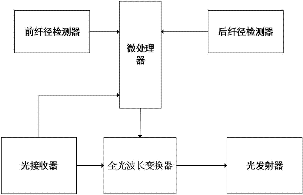
[0005] The invention provides a method and device for reducing splice loss in the optical transmission process, which solves the problem of large splice loss in the existing optical transmission process

Method used


Image

  • Method and apparatus for reducing the continuous loss in light transmission process
  • Method and apparatus for reducing the continuous loss in light transmission process

Examples


Embodiment Construction

[0035] The present invention will be further described below in conjunction with embodiment.

[0036] A method for reducing splicing loss during optical transmission, comprising the steps of:

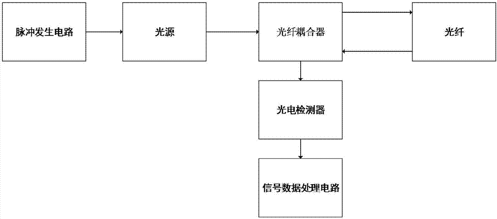
[0037] Step 1: Use the front fiber diameter detector to detect the fiber radius of the front section of the fiber optic connector, and transmit the detected fiber radius of the front section to the microprocessor. The method used by the front fiber diameter detector to detect the radius of the front section of the optical fiber is the backscattering method. The specific process of the backscattering method is that the light wave emitted by the light source enters the optical fiber through the fiber coupler, and the scattered light wave is reflected into the fiber coupler. After detection by the fiber coupler, it is transmitted to the photoelectric converter, and then the radius of the fiber can be analyzed by the signal data processing circuit. Mainly by analyzing the intensity of the ...


PUM


Abstract

The invention provides a method and device for reducing splicing loss in the optical transmission process, belonging to the field of optical transmission, the device includes a front fiber diameter detector, a rear fiber diameter detector, a microprocessor, an optical receiver, and an all-optical wavelength conversion devices and light emitters. Use the front fiber diameter detector and the rear fiber diameter detector to detect the radius of the optical fiber at both ends of the optical fiber connector; use the optical receiver to detect the wavelength of the light wave incoming from the front fiber, and use the normalized frequency formula of the fiber to calculate the fiber at the front transmission mode, and then use the normalized frequency of the front fiber to back-calculate the transmission wavelength of the rear fiber, so that the transmission mode of the rear fiber is the same as that of the front fiber, which can greatly reduce the dispersion loss caused by various transmission modes. It is good to reduce the loss of light transmission in the optical fiber, making the light transmission farther and more stable.

Description

technical field [0001] The invention relates to the field of optical transmission, in particular to a method and device for reducing splice loss in the optical transmission process. Background technique [0002] Optical fiber connector is a device for detachable (movable) connection between optical fiber and optical fiber. It precisely butts the two end faces of optical fiber so that the optical energy output by the transmitting optical fiber can be coupled to the receiving optical fiber to the maximum extent. And to minimize the impact on the system due to its intervention in the optical link, this is the basic requirement of the fiber optic connector. To a certain extent, fiber optic connectors affect the reliability and performance of optical transmission systems. [0003] The transmission loss caused by the use of optical fiber mainly includes two types: splicing loss and non-splicing loss. The transmission loss characteristic of optical fiber is one of the most import...

Claims


Application Information

Patent Timeline
IPC IPC(8): H04B10/2513
CPCH04B10/2513
Inventor 曹蕊
Owner GUANGZHOU KAIYAO ASSET MANAGEMENT CO LTD
Learn More