Cavity equipment convenient to radiate

A cavity and equipment technology, applied in the construction parts of electrical equipment, electrical equipment housing/cabinet/drawer, cooling/ventilation/heating transformation, etc., can solve the problem of metal packaging that cannot play the role of sealing, mechanical support and physical protection Problems such as poor heat dissipation of the shell and poor stress on the joints of the components have achieved the effects of lowering the temperature, enhancing the structural strength, and reducing the production process

Inactive Publication Date: 2017-06-20
SICHUAN LAIYUAN TECH CO LTD
7 Cites 1 Cited by

AI-Extracted Technical Summary

Problems solved by technology

[0005] Most of the existing shells are assembled structures, which are not only inconvenient to assemble, but also the joints of the components are not well stressed, and cannot play a good role in sealing, mechanical support and physical protecti...

Method used

Wherein, the integrated molding of the cavity body can realize the disposable encapsulation molding of the microwave circuit, and reduce the production process; the first groove 2 and the second groove 4 provided can increase the heat dissipation area of ​​the cavity body, Accelerate the heat dissipation speed; the heat sink 3 arranged in the second groove 4 c...

Abstract

The invention discloses cavity equipment convenient to radiate. The cavity equipment comprises a cavity body; a concave cavity is formed in the upper surface of the cavity body; the cavity body is of an integrated structure; a first groove is formed in each of the left outer side surface and the right outer side surface of the cavity body separately; a plurality of heat dissipation sheets are arranged in the first grooves; a plurality of second grooves are also formed in each of the left outer side surface and the right outer side surface of the cavity body separately; and the second grooves and the first grooves are not crossed. By virtue of the integrated cavity equipped with heat dissipation grooves, one-time packaging and forming of a microwave circuit can be realized, production processes can be reduced, the heat dissipation area can be enlarged, and operating reliability of electronic elements can be improved.

Application Domain

Hermetically-sealed casingsCooling/ventilation/heating modifications

Technology Topic

Heat sinkMicrowave

Image

  • Cavity equipment convenient to radiate
  • Cavity equipment convenient to radiate

Examples

  • Experimental program(1)

Example Embodiment

[0025] Example
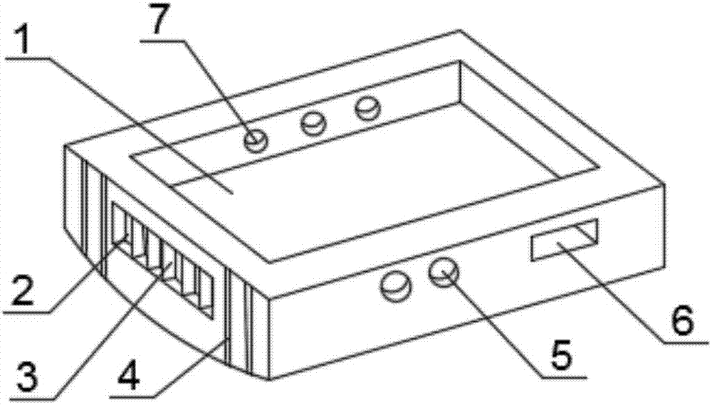
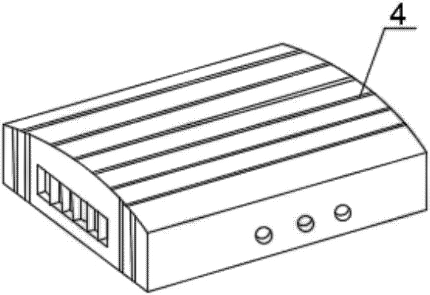
[0026] Such as figure 1 with figure 2 As shown, this embodiment provides a cavity device that facilitates heat dissipation. The upper surface of the cavity body is provided with a cavity 1, the cavity body is an integrated structure, and the left and right outer sides of the cavity body are respectively provided There is a first groove 2 in which a plurality of heat sinks 3 are arranged; the left and right outer sides of the cavity body are also respectively provided with a plurality of second grooves 4, and the second grooves 4 Do not intersect the first groove 2; the lower surface of the cavity body is arc-shaped, and the lower surface of the cavity body is provided with a plurality of second grooves 4; in addition, the first groove 2, the heat sink 3 and the second The surface of the groove 4 is coated with heat dissipation paint.
[0027] The front side of the cavity body is provided with a first round hole 5 and a square hole 6. The center lines of the first round hole 5 and the square hole 6 are perpendicular to the front side of the cavity body, and the first round hole 5 and the square hole 6 are both It is a through hole, and one end of the first round hole 5 and the square hole are both located on the side of the cavity 1; the first round hole 5 is provided with a radio frequency connector, and the square hole 6 is provided with a micro-rectangular connector; A second round hole 7 is provided on the back side. The center line of the second round hole 7 is perpendicular to the back side of the cavity body. The second round hole 7 is a through hole, and one end of the second round hole 7 is located on the side surface of the cavity 1. ; The second round hole 7 is provided with a glass insulator.
[0028] In this embodiment, the number of first round holes 5 is two, the number of square holes 6 is one, and the number of second round holes 7 is three.
[0029] When implementing this embodiment, the first round hole 5 is used to lead out the corresponding pin through the radio frequency connector; the square hole 6 is used to lead out the corresponding pin through the micro-rectangular connector; and the glass insulator is used to support the passage through the second The wires of the round hole 7 are insulated and can be used to transmit high-frequency and low-frequency signals.
[0030] Among them, the cavity body is integrally formed to realize the one-time packaging and molding of the microwave circuit and reduce the production process; the first groove 2 and the second groove 4 provided can increase the heat dissipation area of ​​the cavity body and accelerate the heat dissipation speed ; The heat sink 3 arranged in the second groove 4 can not only increase the heat dissipation area of ​​the cavity body to help heat dissipation, but also play a supporting role, enhance the structural strength of the cavity body, and increase the service life; the heat dissipation coating can improve the object The heat dissipation efficiency of the surface reduces the temperature of the object system.

PUM

no PUM

Description & Claims & Application Information

We can also present the details of the Description, Claims and Application information to help users get a comprehensive understanding of the technical details of the patent, such as background art, summary of invention, brief description of drawings, description of embodiments, and other original content. On the other hand, users can also determine the specific scope of protection of the technology through the list of claims; as well as understand the changes in the life cycle of the technology with the presentation of the patent timeline. Login to view more.

Similar technology patents

Transverse stabilizing rod connecting device for automobile front axle

InactiveCN105270130AIncreased force capacity and service lifeReduce production process
Owner:SINO TRUK JINAN POWER

Automatic detection method

Owner:SUZHOU JINGLAI OPTO CO LTD +1

Classification and recommendation of technical efficacy words

  • Reduce production process
  • Increase cooling area

Synthetic method of 2-cyanogroup-4-nitro-6-bromaniline diazosalt

ActiveCN101671272AReduce production processThree wastes are produced less
Owner:HANGZHOU JIHUA JIANGDONG CHEMICAL CO LTD

OLED display device

Owner:TCL CHINA STAR OPTOELECTRONICS TECH CO LTD

Measurement device, with step-shaped cone, absorbing all energy of high-energy laser

ActiveCN103471713AIncrease cooling areareduce power density
Owner:INST OF APPLIED ELECTRONICS CHINA ACAD OF ENG PHYSICS

LED light fitting

Owner:NANKER GUANGZHOU SEMICON MFG
Why Eureka
Try Eureka