
Multi-beam load front-end architecture of mobile communication satellite

A communication satellite and multi-beam technology, which is applied in the field of geostationary mobile communication satellite payload, can solve the problems of large output power difference, waste of satellite resources, long radio frequency cable size, etc., and achieve the effect of weight reduction and low loss

Active Publication Date: 2017-06-23
XIAN INSTITUE OF SPACE RADIO TECH
View PDF5 Cites 0 Cited by
  • Summary
  • Abstract
  • Description
  • Claims
  • Application Information

AI Technical Summary

Problems solved by technology

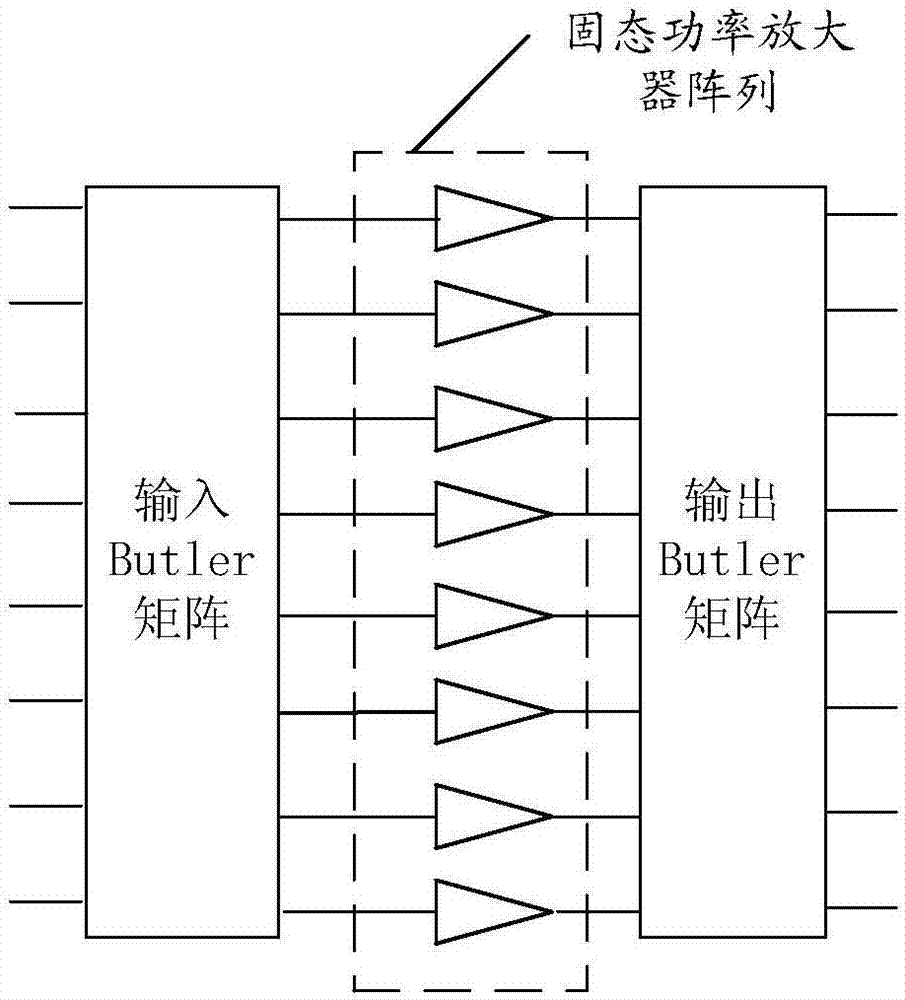
[0003] Public information shows that foreign mobile communication satellites usually use MPA to realize the business concentration function of mobile communication satellites, but there is no detailed report
Relevant domestic units have studied the use of MPA in the front-end of multi-beam loads of mobile communication satellites, and solved the problem of large output power difference of solid-state power amplifiers in MPA and large waste of satellite resources under the condition of feed multiplexing
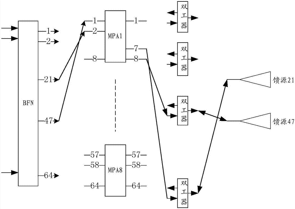
However, there are still the following problems in actual use: In the shared transceiver system, there is a duplexer between the MPA and the feed array. If a duplexer is randomly selected for each feed and then connected to the output port of the MPA, due to the space on the star Due to the limitation, the size of the RF cable is longer, which will lead to deterioration of various performance indicators such as volume, weight, loss, output power, and return G / T value.
[0004] Since mobile communication satellite loads usually use large-scale deployable antennas and array transponders, the requirements for the volume, weight, loss, output power, and return G / T value of the load are very strict, and the existing ones have been publicly reported. technology does not meet the requirements

Method used


Image

  • Multi-beam load front-end architecture of mobile communication satellite
  • Multi-beam load front-end architecture of mobile communication satellite
  • Multi-beam load front-end architecture of mobile communication satellite

Examples


Embodiment example

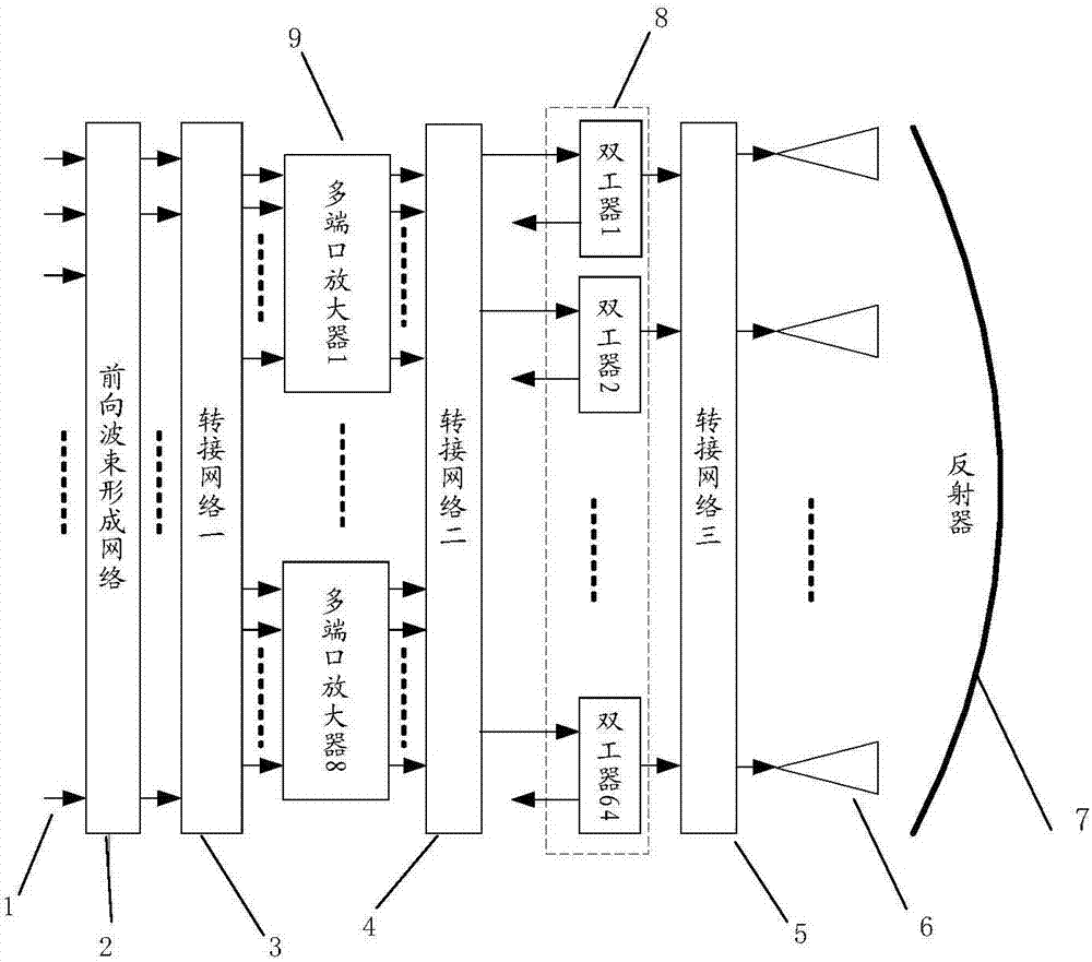
[0100] Such as figure 2 with Figure 4 As shown, the system has 109 beams for receiving and transmitting, and 64 feed sources can be shared by transmitting and receiving through duplexers.

[0101] After optimizing the excitation coefficients of each beam and completing the layout of the duplexer and feed array in the satellite communication cabin, the Beam i , i=1, 2, ... 109 and L 0 ;

[0102] The above genetic algorithm is implemented by programming, and the actual switching network obtained is as follows: figure 2 As shown, the design value of the ratio of the output power of 109 beams to the total power of 64 solid-state power amplifiers in the system is as follows Figure 4 As shown, the test values ​​are as Figure 5 As shown, the horizontal axis represents the beam number, and the vertical axis represents the ratio of the output power of each beam working alone to the system output power.


PUM


Abstract

The invention provides a multi-beam load front-end architecture of a mobile communication satellite. The multi-beam load front-end architecture comprises a forward beam forming network BFN, three transition networks, a multi-port amplifier array, a duplexer array, a feed source array, and a reflector. A signal, which enters into a beam, is subjected to power allocating, amplitude weighting and phase weighting through the forward beam forming network. The signal is amplified by a multi-port amplifier. The transmit-receive sharing of a feed source is realized by a duplexer. The feed source array outputs a signal to irradiate a reflective surface, so that the radiation of a radio frequency signal is realized. A transition network 1 is connected with a BFN output port and an input port of a MPA. A transition matrix 2 is connected with the output port of the MPA and a duplexer in the duplexer array. A transition network 3 is connected with the duplexer in the duplexer array and a feed source. According to the technical scheme of the invention, the multi-beam load of the mobile communication satellite is low in feeder loss and weight, and good in service centralization capability.

Description

technical field [0001] The invention relates to a multi-beam load front end of a mobile communication satellite, which is suitable for the payload of a mobile communication satellite in a geostationary orbit. Background technique [0002] In recent years, China has started the research and development of geostationary orbit mobile communication satellites. The service area of ​​a mobile communication satellite is generally composed of multiple beams, and the business of a mobile communication satellite changes over time between different beams in the service area, that is, a large number of services may be concentrated in one or several beams at the same time; Due to the limitation of space and energy, there are strict requirements on the volume, weight and power consumption of the load and its front end, and strive to save and increase efficiency. [0003] Public information shows that foreign mobile communication satellites usually use MPA to realize the business concentr...

Claims


Application Information

Patent Timeline
Patent Type & Authority Applications(China)
IPC IPC(8): H04B7/185
CPCH04B7/1853
Inventor 陈博崔兆云任建周兰兰李荣军黄齐波王五兔唐其林
Owner XIAN INSTITUE OF SPACE RADIO TECH
Learn More