
Mooring unmanned aerial vehicle

A drone and tethering technology, applied in the field of drones, can solve the problems of scattered on the ground, inconvenient cable recycling, high power consumption, etc., to achieve the effect of reducing power loss, low power, and low power consumption

Pending Publication Date: 2017-06-27
TIANXUN INNOVATION BEIJING TECH CO LTD
View PDF0 Cites 6 Cited by
  • Summary
  • Abstract
  • Description
  • Claims
  • Application Information

AI Technical Summary

Problems solved by technology

The length of battery life seriously affects the efficiency of mission execution. With the development of various miniaturized and modular UAV systems, traditional tethered UAVs consume a lot of power, and traditional tethered UAVs land first. , the cables are scattered on the ground, and then the cables are recycled. There is a problem of inconvenient cable recycling. It is very necessary to design a general energy-saving, high-efficiency, long-lasting, and easy-to-control tethered UAV system

Method used


Image

  • Mooring unmanned aerial vehicle
  • Mooring unmanned aerial vehicle
  • Mooring unmanned aerial vehicle

Examples


Embodiment 1

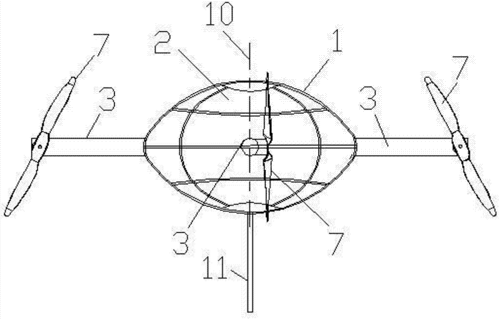
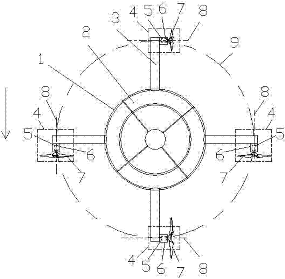
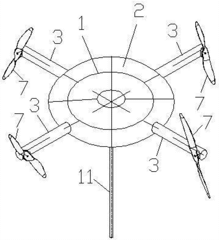
[0023] Depend on Figure 1-Figure 3 A tethered unmanned aerial vehicle shown includes a balloon 2 arranged in a ball cage 1, the balloon 2 is a hydrogen balloon or a helium balloon, the cross section of the balloon 2 is circular, and the longitudinal section of the balloon 2 is a horizontal width Flat shape greater than the height, preferably, the longitudinal section of the balloon 2 is an ellipse, and the major axis of the ellipse is a horizontal line, the minor axis is a vertical line, and the minor axis is the vertical central axis 10 of the balloon 2 , the balloon 2 is a body of revolution around its vertical central axis 10 times. The shape of the cage 1 is adapted to the shape of the balloon 2.

[0024] Four machine arms 3 are evenly spaced around the outer ring of the ball cage 1, the machine arms 3 are fixed outside the ball cage 1, one end of the machine arm 3 is connected to the inner end of the ball cage 1, and the other end is pointing to the outside of the ball ...

Embodiment 2

[0030] Depend on Figure 4-Figure 6 A tethered unmanned aerial vehicle shown is different from Embodiment 1 in that: the inner end of the machine arm 3 is connected to the ball cage 1 through the machine arm driving device 12, and the four machine arms 3 are respectively connected to four machine arm drives. The device 12 and the machine arm driving device 12 are arranged in the middle position in the height direction of the ball cage 1 .

[0031] The arm driving device 12 includes a stepping motor 13 fixed on the outside of the ball cage 1, an outer support 19 fixedly connected to the outside of the ball cage 1, a transmission shaft mounting seat 17 fixed on the outside of the outer support 19, and a stepping motor 13 The driving transmission shaft 18, the belt transmission device and the casing 20 fixedly connected to the outside of the ball cage 1; Inside, vice versa, the sleeve 20 is a circular tube, the sleeve 20, the drive shaft and the machine arm are connected sequent...


PUM


Abstract

The invention discloses a mooring unmanned aerial vehicle, and belongs to the technical field of unmanned aerial vehicles. The mooring unmanned aerial vehicle comprises a balloon mounted in a ball cage, and the balloon is a hydrogen balloon or a helium balloon; four machine arms distributed evenly at intervals are arranged around the outer ring of the ball cage, one end of each machine arm is an inner end connected to the ball cage, and the other end of each machine arm is an outer end pointing to the outside the ball cage; a rotor assembly is arranged at the outer end, pointing to the outside the ball cage, of each machine arm, each rotor assembly comprises a propeller motor and a propeller driven by the propeller motor, and a propeller center axis extends horizontally; and balloon vertical center axes surrounded by four propellers on the four machine arms are arranged along a circumferential line sequentially, and the center axis of each propeller is tangent to the circumferential line. According to the mooring unmanned aerial vehicle, cables are easy to recycle, and the mooring unmanned aerial vehicle is capable of realizing the hover in unlimited time and space.

Description

technical field [0001] The invention belongs to the technical field of unmanned aerial vehicles, and in particular relates to a tethered unmanned aerial vehicle. Background technique [0002] Early unmanned aerial vehicles were more used as target aircraft and reconnaissance aircraft for experimental training, reconnaissance and surveillance. Development and application, unmanned aerial vehicles (UAVs) have gradually developed into a new type of air power, which can play an important role in boring mission fields, harsh environment mission fields and dangerous mission fields. In recent years, countries all over the world are vigorously developing multi-rotor UAVs, which have been widely used in both military and civilian applications. Multi-rotor drones are small in size, low in cost, can hover at fixed points, and can take off and land vertically. Therefore, they can be used for military tasks such as transporting materials, battlefield surveillance, and border inspections...

Claims


Application Information

Patent Timeline
IPC IPC(8): B64B1/20B64B1/32B64B1/50
CPCB64B1/20B64B1/32B64B1/50
Inventor 王川杨威
Owner TIANXUN INNOVATION BEIJING TECH CO LTD
Learn More