Indoor navigation positioning method, system, to-be-positioned device and anchor nodes

A positioning device and indoor navigation technology, applied in the field of indoor positioning systems with high navigation accuracy, can solve problems such as poor positioning accuracy and complex positioning method processes.

Inactive Publication Date: 2017-06-27
上海器魂智能科技有限公司
View PDF3 Cites 16 Cited by
  • Summary
  • Abstract
  • Description
  • Claims
  • Application Information

AI Technical Summary

Problems solved by technology

[0003] In view of the above problems, the present invention provides an indoor navigation and positioning method, system, equipment to be positioned and anchor nodes to solve the problems of complicated process and poor positioning accuracy of existing positioning methods

Method used


Image

  • Indoor navigation positioning method, system, to-be-positioned device and anchor nodes
  • Indoor navigation positioning method, system, to-be-positioned device and anchor nodes
  • Indoor navigation positioning method, system, to-be-positioned device and anchor nodes

Examples


Embodiment 1

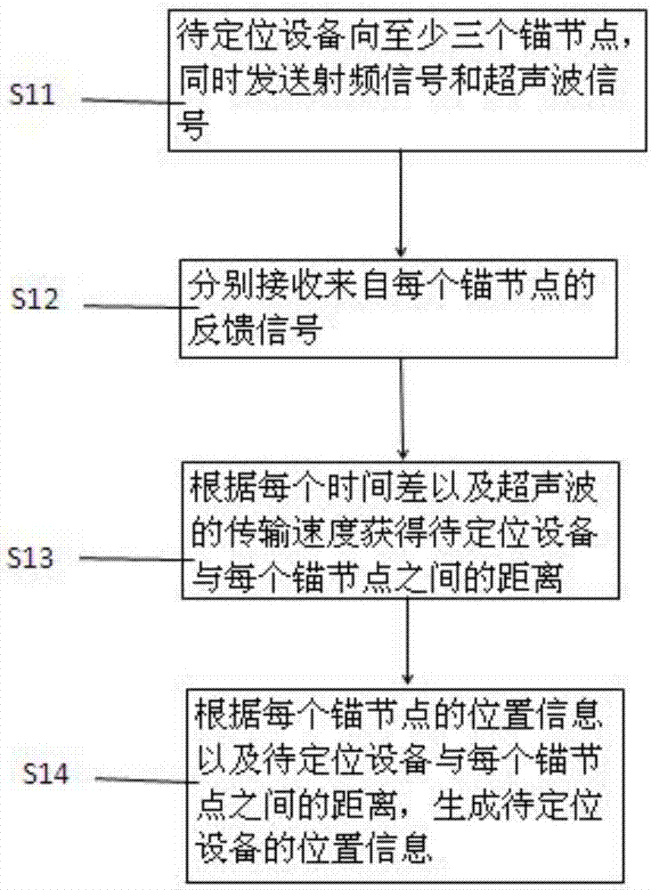
[0108] This embodiment relates to an indoor navigation and positioning method. The above-mentioned indoor navigation and positioning method has a schematic flow chart as shown in image 3 shown, including the following steps:

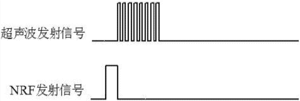
[0109] Step S11: The device to be positioned simultaneously sends radio frequency signals and ultrasonic signals to at least three anchor nodes, and the at least three anchor nodes are distributed in different directions relative to the device to be positioned.

[0110] Wherein, at least three anchor nodes, such as anchor node A, anchor node B, anchor node C and so on.

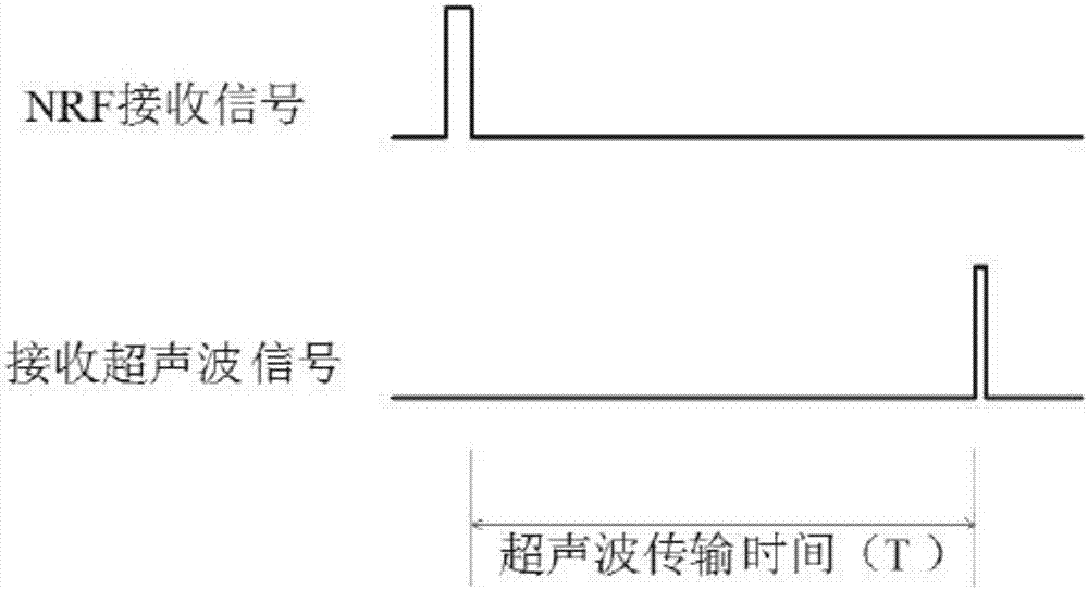
[0111] Step S12: Receiving a feedback signal from each anchor node respectively, the feedback signal being the time difference between the radio frequency signal and the ultrasonic signal received by the anchor node.

[0112] For example, the device to be positioned sends the radio frequency signal and the ultrasonic signal to the anchor node A at the same time, and the anchor node A f...

Embodiment 2

[0119] like Figure 4 As shown, on the basis of Embodiment 1, the indoor navigation and positioning method of this embodiment also includes setting a preset time t 0 . Proceed as follows:

[0120] Step S11: The device to be positioned simultaneously sends radio frequency signals and ultrasonic signals to at least three anchor nodes, and the at least three anchor nodes are distributed in different directions relative to the device to be positioned.

[0121] Wherein, at least three anchor nodes, such as anchor node A, anchor node B, anchor node C and so on.

[0122] Step S12: Receiving a feedback signal from each anchor node respectively, the feedback signal being the time difference between the radio frequency signal and the ultrasonic signal received by the anchor node.

[0123] For example, the device to be positioned sends the radio frequency signal and the ultrasonic signal to the anchor node A at the same time, and the anchor node A first at t 1 time RF signal is recei...

Embodiment 3

[0138] like Figure 5 As shown, on the basis of Embodiment 1, in the navigation and positioning method of this embodiment, each step is specifically as follows:

[0139] Step S11 in this embodiment is specifically: while the device to be positioned sends radio frequency signals to at least three anchor nodes, at least three ultrasonic signals are sequentially sent at least three times according to the preset ultrasonic delay time each time;

[0140] Step S12: Receive the feedback signal from each anchor node respectively, the feedback signal is the time difference between the radio frequency signal and the ultrasonic signal received by the anchor node;

[0141] For example, the device to be positioned sends the radio frequency signal and the ultrasonic signal to the anchor node A at the same time, and the anchor node A first at t 1 time RF signal is received, then at t 2 time to receive the ultrasonic signal, t 2 with t 1 The time difference between is the ultrasonic trans...


PUM


Abstract

The invention relates to an indoor navigation positioning method, a system, a to-be-positioned device and anchor nodes. The method comprises the following steps: simultaneously sending a radio frequency signal and an ultrasonic signal to the anchor nodes distributed along different directions by the to-be-positioned device, and then calculating distances between the to-be-positioned device and the anchor nodes and generating position information of the to-be-positioned device, according to the time difference of the received radio frequency signal and ultrasonic signal and the ultrasonic transmission rate. Compared with the prior art, the indoor navigation positioning method, the device and the system thereof provided by the invention have the advantages of simple and easy operation, low power consumption, high positioning precision, large navigation area and low cost.

Description

technical field [0001] The invention relates to a navigation control system and method, in particular to an indoor positioning system and method with high navigation accuracy. Background technique [0002] At present, the solutions adopted in the navigation and positioning industry include: the combined navigation solution of ultrasonic and Zigbee, the software program is more complicated to realize the function, the power consumption is relatively large, and the hardware cost of purchasing Zigbee chips is high; the UWB ranging navigation solution is adopted, and the UWB high High-frequency electromagnetic waves are greatly disturbed by metal shielding and electric fields, and the application occasions are limited, and the positioning accuracy of the system is poor, generally >50cm; using laser radar navigation and distance measurement, laser distance measurement is greatly affected by the environment, such as transparent glass, strong light When the distance cannot be me...

Claims


Application Information

Patent Timeline
Patent Type & Authority Applications(China)
IPC IPC(8): G01C21/20G01S5/02G01S5/10G01S5/26
Inventor 陈晓禾赵海青阮胜田黄俊杰侯迎超吴玲俐
Owner 上海器魂智能科技有限公司
Why Eureka
Try Eureka