Main switch fault detection method for asymmetric half-bridge-type power converter of switched reluctance motor
A technology for switched reluctance motors and power converters, applied in the field of speed-regulated motors, can solve the problems of limited diagnostic content and scope of application, fault feature quantities, increased system cost and complexity, etc., and achieves a simple, convenient and low-cost detection method. , the effect of a wide range of practical engineering application value
- Summary
- Abstract
- Description
- Claims
- Application Information
AI Technical Summary
Problems solved by technology
Method used
Image
Examples
Embodiment 1
[0035] Embodiment 1: When the switched reluctance motor is running at high speed with load, the open circuit fault detection of the normally closed main switch is performed.
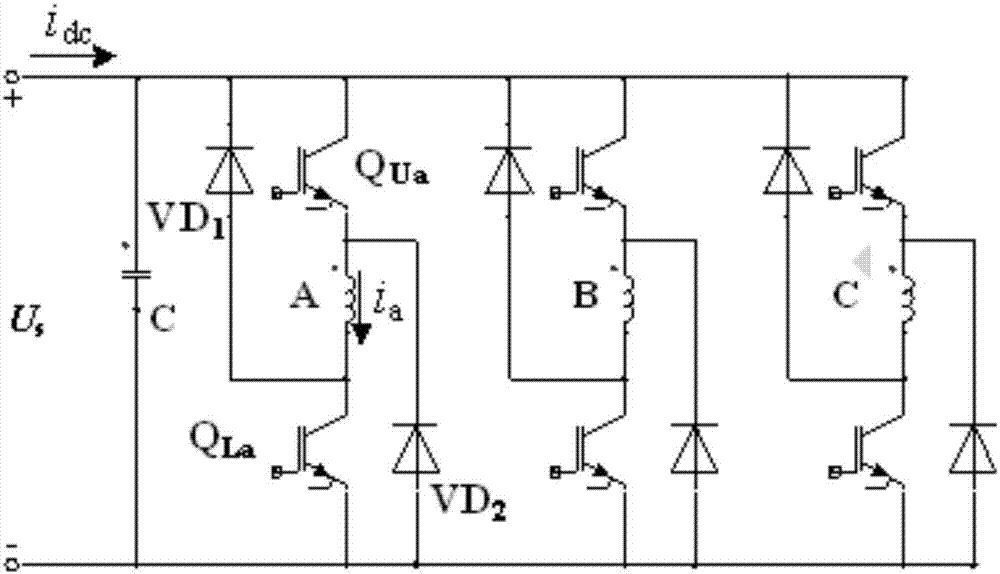
[0036] Such as figure 1 As shown, it is a three-phase switched reluctance motor asymmetrical half-bridge power converter topology. Winding A, winding B, and winding C are three-phase windings of switched reluctance motor. Each phase winding is composed of two main switches QU, QL is connected to two freewheeling diodes VD1 and VD2, and US is the DC power supply voltage. In practice, the single-tube chopping method is often used. During the conduction period of the A-phase winding, the upper main switch QUa is always closed, which is called a "normally closed" main switch, and the lower main switch QLa implements chopping control, which is called a "chopping" main switch. . The power supplies power to the winding. When the lower main switch is closed, the voltage at both ends of the conducting phase win...
Embodiment 2
[0069] Embodiment 2: When the switched reluctance motor is running at low speed with load, open-circuit fault detection of the chopper main switch.
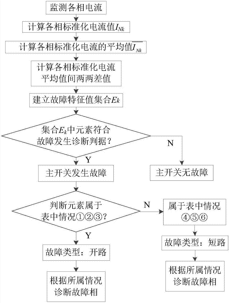
[0070] The main circuit topology and detection process of the three-phase asymmetrical half-bridge power converter are the same as those in the first embodiment. When the three-phase switched reluctance motor is running, when the speed n=550r / min, the load T L=5N·m, the actual fault detection results are as follows Figure 4 shown. 285ms ago, element E AB =E AC =E BC =0, after this moment, I C down to zero, I A with I B but remain the same. After another 0.7ms, |E AC |=|E BC |=0.2>0.05, |E AB |=0AC >p o ,E BC >p o , belongs to the situation ③ in Table 1, then it can be diagnosed that the main switch fault type is open circuit, and the fault phase is C phase.
Embodiment 3
[0071] Embodiment 3: When the switched reluctance motor is running at high speed with load, the normally closed main switch short-circuit fault detection.
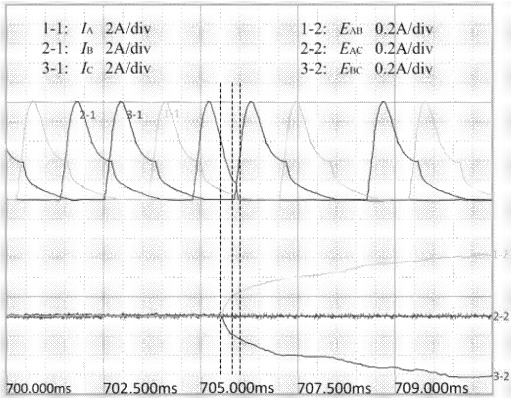
[0072] The main circuit topology and detection process of the three-phase asymmetrical half-bridge power converter are the same as those in the first embodiment. When the three-phase switched reluctance motor is running, when the speed n=2000r / min, the load T L =5N·m, the actual fault detection results are as follows Figure 5 shown. 725ms ago, element E AB =E AC =E BC =0, after this moment, I B down to zero, I A with I C but remain the same. After another 0.4ms, |E AB |=|E BC |=0.2>0.05, |E AC |=0BC >p s ,E AB s , belongs to the situation ⑤ in Table 1, then it can be diagnosed that the main switch fault type is short circuit, and the fault phase is B phase.
PUM
 Abstract
Description
Claims
Application Information
 - R&D
- Intellectual Property
- Life Sciences
- Materials
- Tech Scout
- Unparalleled Data Quality
- Higher Quality Content
- 60% Fewer Hallucinations
Browse by: Latest US Patents, China's latest patents, Technical Efficacy Thesaurus, Application Domain, Technology Topic, Popular Technical Reports.
© 2025 PatSnap. All rights reserved.Legal|Privacy policy|Modern Slavery Act Transparency Statement|Sitemap|About US| Contact US: help@patsnap.com


