
Device and method for demonstration of controlling motor rotation speed

A technology of motor speed and demonstration device, which is applied in the direction of educational appliances, instruments, teaching models, etc., and can solve problems such as poor contact of resistance switches and lack of ampere force demonstration experiments

Pending Publication Date: 2017-06-27
QIQIHAR UNIVERSITY
View PDF6 Cites 1 Cited by
  • Summary
  • Abstract
  • Description
  • Claims
  • Application Information

AI Technical Summary

Problems solved by technology

Over the years, in order to help students correctly understand and apply Ampere force, some demonstration experiments have been set up in conjunction with teaching, such as the demonstration experiment of Ampere force of rectangular coil, DC motor, and the micro-mechanism experiment instrument of Ampere force designed by the inventor of this patent, etc. In the previous demonstration experiments, the position of the magnet relative to the rotor remained unchanged. In the previous demonstration experiments of motor speed regulation, the input voltage of the motor was changed, and the control of the rotor speed was changed by controlling the change of the current intensity supplied to the rotor. However, there is a lack of Ampere force demonstration experiments for variable magnetic fields. How to realize the Ampere force demonstration experiments for variable magnetic fields with obvious effects, simple structure, low cost, and meeting the physical knowledge requirements of junior and high school students in universities, this patent will solve the problem. this problem

Method used


Image

  • Device and method for demonstration of controlling motor rotation speed
  • Device and method for demonstration of controlling motor rotation speed
  • Device and method for demonstration of controlling motor rotation speed

Examples


Embodiment Construction

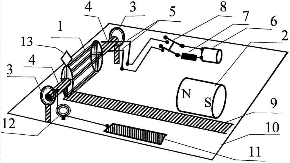
[0035] as attached figure 1 : A demonstration device and method for controlling the speed of a motor, mainly composed of a rotor (1), a magnet (2), a rotor support ring (3), a power supply (6), a current limiting resistor (7), a switch (8), colored paper sheet (13), scale (9), insulating plastic plate (10), spring balance (11) and fixed pulley (12), the feature is: the rotor shaft (4) of the rotor (1) passes through the rotor support ring (3), the rotor support ring (3) is fixed on a straight rod that is vertical and fixed on the insulating plastic plate 10, and the rotor (1) is a DC motor that is unloaded from a brushed toy DC motor for the rotor of a DC motor The rotor (or a rotor made of a self-winding rectangular wire frame), the rotor shaft (4) is in contact with the brush (5) fixed on the insulating plastic plate (10), and the brush (5) passes through the wire, the current limiting resistor (7) and the switch (8) are connected with the power supply (6) fixed on the insu...


PUM


Abstract

The present invention provides a device and method for demonstration of controlling motor rotation speed, belonging to the physics teaching experiment apparatus field. The device mainly comprises: a rotor, a magnet, a rotor support ring, a power supply, a current-limiting resistor, a switch, a color paper, a scale, an insulation plastic plate, an elastic scale and a fixed pulley. The rotor shaft of the rotor passes through the rotor support ring, the rotor support ring is fixed on a straight bar perpendicular to and fixed on the insulation plastic plate, the rotor is the rotor of a direct current motor, the rotor shaft is in contact with a brush on the insulation plastic plate, the scale being perpendicular to the rotor and fixed on the insulation plastic plate; one end of soft string incapable of expansion is fixed on the rotor shaft, the other end of the soft string is connected with the hook of the elastic scale through the fixed pulley, and the elastic scale and the scale are fixed in parallel on the insulation plastic plate. The device and method for demonstration of controlling the motor rotation speed have active meanings for understanding content including Ampere force, magnetic moment and the like, avoid the phenomenon that resistance changing is easy to cause bad switch contact because of speed regulation of a motor in prior art, the manufacturing is very simple and the effect is obvious.

Description

technical field [0001] The patent of the present invention relates to a device and a method for demonstrating magnetic control of rotational speed, and belongs to the field of physics teaching experiment instruments. Background technique [0002] In college physics or middle school physics courses, Ampere force is an important content, and the application of Ampere force is the content that everyone pays attention to. Over the years, in order to help students correctly understand and apply Ampere force, some demonstration experiments have been set up in conjunction with teaching, such as the demonstration experiment of Ampere force of rectangular coil, DC motor, and the micro-mechanism experiment instrument of Ampere force designed by the inventor of this patent, etc. In the previous demonstration experiments, the position of the magnet relative to the rotor remained unchanged. In the previous demonstration experiments of motor speed regulation, the input voltage of the moto...

Claims


Application Information

Patent Timeline
IPC IPC(8): G09B23/18
CPCG09B23/181
Inventor 梁法库郑亚辉吴桐
Owner QIQIHAR UNIVERSITY
Learn More