Phase locked loop circuit based on spin oscillator

A phase-locked loop and oscillator technology, applied in the field of electronic circuits, can solve problems such as the narrow frequency tuning range of voltage-controlled oscillators, the inability to integrate in chips, and the inability to meet the needs of high-frequency circuits.

Active Publication Date: 2017-06-27
INST OF PHYSICS - CHINESE ACAD OF SCI
View PDF6 Cites 1 Cited by
  • Summary
  • Abstract
  • Description
  • Claims
  • Application Information

AI Technical Summary

Problems solved by technology

Both the inductance L and the capacitance C in the LC oscillator are difficult to miniaturize, which is not conducive to integration
Even in the current large-scale integrated circuit chips, in order to achieve large inductance values ​​and large capacitance values, external inductors and capacitors are generally used instead of being directly integrated into the chip.
Crystal oscillators also have difficulties in miniaturization
Therefore, the current phase-locked loop can no longer meet the needs of integrated circuit development
On the other hand, the current LC oscillators and crystal oscillators have relatively low output frequencies, which cannot meet the needs of high-frequency circuits.
Moreover, large inductance L and capacitance C are required to achieve high frequencies, which further exacerbates the aforementioned miniaturization difficulties
In addition, the frequency tuning range of the existing voltage-controlled oscillators is relatively narrow, thus limiting the versatility of the phase-locked loop, and it is necessary to design a specific phase-locked loop for a specific circuit (or frequency)

Method used


Image

  • Phase locked loop circuit based on spin oscillator
  • Phase locked loop circuit based on spin oscillator
  • Phase locked loop circuit based on spin oscillator

Examples


Embodiment Construction

[0019] Exemplary embodiments of the present invention will be described below with reference to the accompanying drawings.

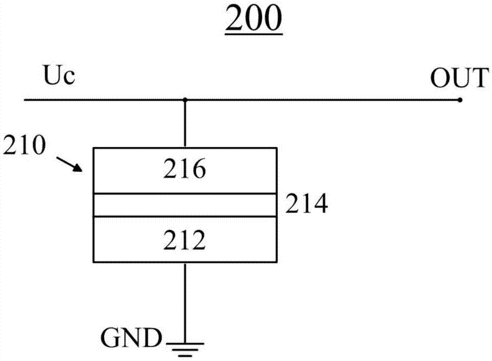
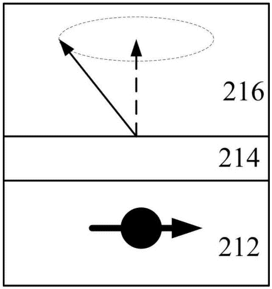
[0020] figure 2 A structural block diagram of a spin oscillator 200 according to an embodiment of the present invention is shown. image 3 The principle of operation of the spin oscillator 200 is schematically shown.

[0021] like figure 2 As shown, the core component of the spin oscillator 200 is a multilayer film structure 210 , which may include a spin injection layer 212 , a spacer layer 214 and a magnetic precession layer 216 .

[0022] The spin injection layer 212 is made of a material capable of generating spin current. It is well known that electrons have spin properties, such as spin-up electrons and spin-down electrons. In an ordinary current, the spin-up electrons and the spin-down electrons are roughly divided, so the ordinary current is non-polarized. When the non-spin-polarized current passes through the spin injection layer 212, it ...


PUM


Abstract

The invention discloses a phase locked loop circuit based on a spin oscillator. The phase locked loop circuit comprises a phase detector, a lowpass filter and the spin oscillator. When a control signal is applied to the spin oscillator, an oscillation signal is generated. The oscillation signal is output through the output end of the phase locked loop circuit and is fed back to the phase detector through a feedback loop which is connected with the output end of the phase locked loop circuit and the phase detector. The spin oscillator may comprise a spin injection layer and a magnetic precession layer arranged on the spin injection layer. When the spin injection layer receives non-spin polarized current input, spin polarized current output is generated. The magnetic precession layer is formed by a magnetic conductive material and receives a spin polarized current from the spin injection layer. In response to the spin polarized current, a magnetic torque of the magnetic precession layer generates precession, thereby generating the oscillation signal.

Description

technical field [0001] The present invention generally relates to electronic circuits, and more particularly, to a spin oscillator-based phase-locked loop circuit and an electronic circuit including the phase-locked loop circuit. Background technique [0002] Phase-locked loop (PLL) is a commonly used electronic component, which is widely used in various electronic circuits and systems. figure 1 A typical phase locked loop 100 is shown, which includes a phase detector 110 , a low pass filter 120 and a voltage controlled oscillator 130 . [0003] The phase detector 110 receives the input signal u i (t), which has frequency ω i , and also receive the output signal u fed back from the output terminal of the phase-locked loop 100 o (t), which has frequency ω o . The phase detector 110 detects the phase difference between these two signals, and converts the detected phase difference signal into a voltage signal u D (t) output. It should be noted that the voltage signal u o...

Claims


Application Information

Patent Timeline
Patent Type & Authority Applications(China)
IPC IPC(8): H03L7/099
CPCH03L7/099
Inventor 魏红祥丰家峰韩秀峰
Owner INST OF PHYSICS - CHINESE ACAD OF SCI
Why Eureka
Try Eureka