
Large compound radiant heating rod and preparation method thereof

A compound radiation and heating rod technology, which is applied in the field of large compound radiation heating rod and its preparation, can solve the problems of short service life, scrapping and high brittleness of the heating rod, and achieve high tensile and flexural strength, increased heating volume, high temperature The effect of excellent strength

Pending Publication Date: 2017-06-27
孙劲腾 +1
View PDF0 Cites 0 Cited by
  • Summary
  • Abstract
  • Description
  • Claims
  • Application Information

AI Technical Summary

Problems solved by technology

At present, the two most widely used heating rods are silicon carbide rods and silicon molybdenum rods. These two heating rods have a short service life. The service life of the atmosphere will be shortened, and silicon carbon rods are the opposite. Oxygen will be taken away from the carbon, which will be gradually eroded, and eventually lead to scrapping and failure to work.
On the other hand, these two kinds of heating rods have low tensile strength at high temperature, high brittleness, and high damage rate in the temperature fragile area. In addition, due to their own weight, the length of the heating rod is limited and cannot be made too long.
The length of the heating rod is limited so that the heat radiation distance in the heating furnace is very short. In order to ensure that the temperature in the heating furnace meets the requirements, the space size in the heating furnace has to be reduced, which limits the mass production of products.
Although a small number of large-scale radiant heating furnaces have appeared at present, they are generally limited to small diameters, no more than 2.5 meters, but the cost is very high, which increases the production cost of large-scale products

Method used


Image

  • Large compound radiant heating rod and preparation method thereof
  • Large compound radiant heating rod and preparation method thereof
  • Large compound radiant heating rod and preparation method thereof

Examples


Embodiment Construction

[0042] In order to clearly illustrate the technical features of this solution, the present invention will be described in detail below through specific implementation modes and in conjunction with the accompanying drawings.

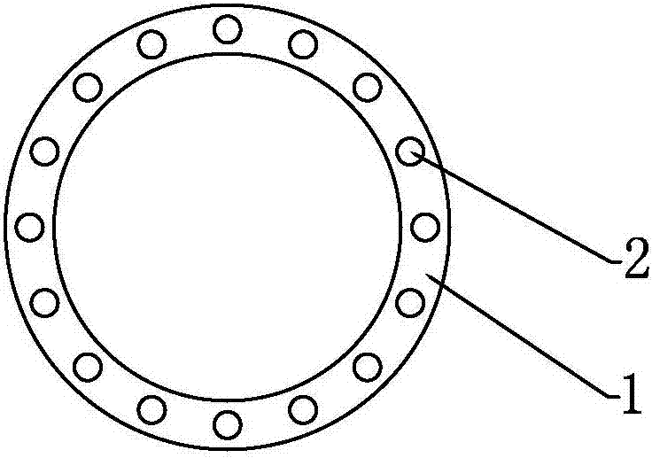
[0043] Such as Figure 1-Figure 3 As shown in , the large-scale composite radiant heating rod in this embodiment includes a fixed sleeve 1 made of insulating material, and several installation column holes are evenly penetrated on the wall of the fixed sleeve 1 along the axis direction of the fixed sleeve 1. 2. The mounting column holes 2 are arranged on the side wall of the fixed sleeve 1 in a circular shape, and a heating rod is inserted in each mounting column hole 2, and the heating rod includes a plurality of rod units The connected heating section 3 and the two conductive cold ends 4 welded to the two ends of the heating section 3, the outer wall of the fixed sleeve 1 adjacent to each mounting column hole 2 are provided with several holes connected ...


PUM

PropertyMeasurementUnit
Lengthaaaaaaaaaa
Lengthaaaaaaaaaa
Outer diameteraaaaaaaaaa

Abstract

The invention discloses a large compound radiant heating rod and a preparation method thereof. The large-scale compound radiant heating rod includes a fixed sleeve of an insulating material. A plurality of mounting column holes are disposed uniformly in a penetrating manner on the tube wall of the fixed sleeve along the axis of the fixed sleeve. A heating rod is inserted in each mounting column hole. A plurality of fixing holes communicating with the mounting column holes are disposed in the outer side wall of the fixed sleeve closely adjacent to each of the mounting column holes. Ceramic consolidation agents are filled in the fixing holes and in the mounting column holes facing the fixing holes. According to the invention, the plurality of heating rods are mounted together in the fixed sleeve, the radiation area and length of the radiated heat by the heating rods to a furnace are increased, the outer layer of fixed sleeve is used as a protective layer, the tensile strength and breaking strength are high, the damage rate of the heating rods are greatly reduced, so that the heating rods can be arbitrarily arranged in the heating furnace to increase the heating capacity of the electric furnace and the processing of various large products is facilitated.

Description

technical field [0001] The invention relates to a large compound radiation heating rod and a preparation method thereof. Background technique [0002] The heating furnace is an important production equipment in the high-temperature sintering fields of electronics, metallurgy, ceramics, and magnetic materials. As the heating element of the heating furnace, the heating rod is hung on the inner wall of the heating furnace. The air in the furnace heats the materials in the furnace, so the performance of the heating rod plays a vital role in the heating efficiency of the furnace. At present, the two most widely used heating rods are silicon carbide rods and silicon molybdenum rods. These two heating rods have a short service life. The service life of the atmosphere will be shortened, but on the contrary, the oxygen will be taken away from the carbon of the silicon carbide rod, which will be gradually eroded, and eventually it will be scrapped and unable to work. On the other ha...

Claims


Application Information

Patent Timeline
IPC IPC(8): H05B3/64H05B3/02H05B3/10H05B3/12
CPCH05B3/02H05B3/10H05B3/12H05B3/64H05B2203/017
Inventor 孙劲腾孙学贤
Owner 孙劲腾
Learn More