Coupling structure of multimode fiber and photoelectric detector

A technology of photodetector and multimode optical fiber, applied in the field of optical fiber communication

Inactive Publication Date: 2017-06-30
SHANGHAI BRANCH FUZHOU GAOYI COMM CO LTD
View PDF4 Cites 4 Cited by
  • Summary
  • Abstract
  • Description
  • Claims
  • Application Information

AI Technical Summary

Problems solved by technology

[0003] In view of the above problems, the object of the present invention is to provide a coupling structure for multimode optical fiber and photodetection sheet, which has the advanta

Method used


Image

  • Coupling structure of multimode fiber and photoelectric detector
  • Coupling structure of multimode fiber and photoelectric detector
  • Coupling structure of multimode fiber and photoelectric detector

Examples


Embodiment Construction

[0019] The present invention will be further described below in conjunction with the accompanying drawings and specific embodiments.

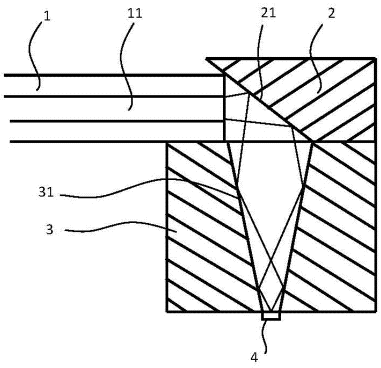
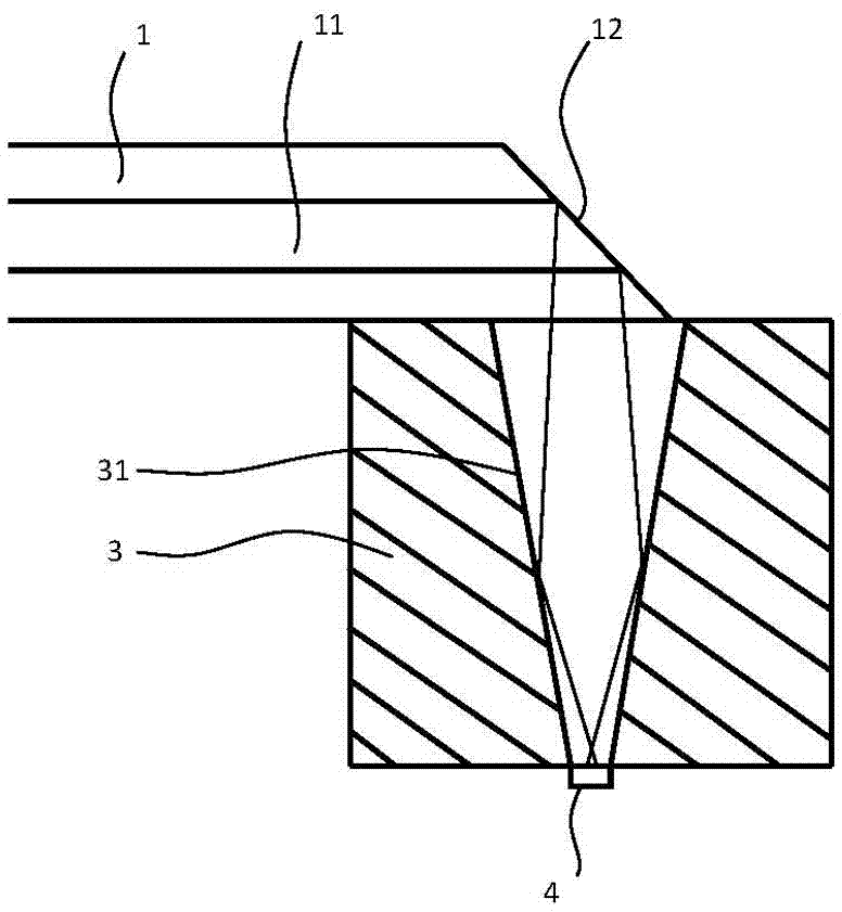
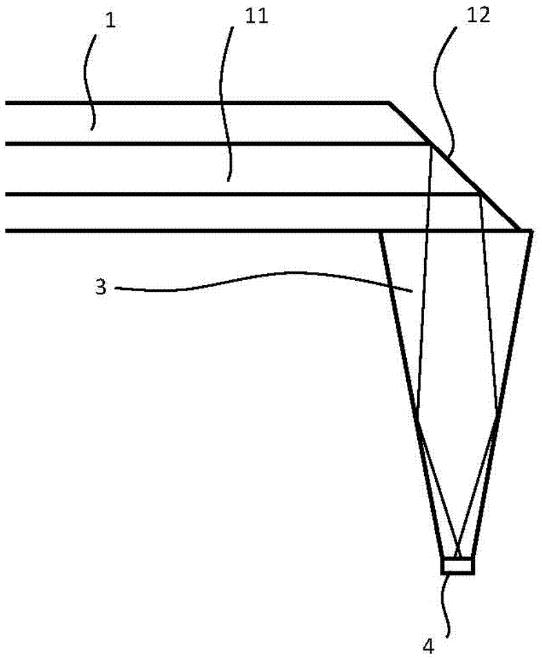
[0020] A coupling structure between a multimode optical fiber and a photodetector, comprising a reflection structure and a convergence structure, the reflection structure is used to reflect all the output light beams of the optical fiber into the input end of the convergence structure; the convergence structure is used In order to realize the transmission and concentration of light beams, its output end is connected with a photodetector; the photodetector is used to realize the reception, coupling and conversion of light beams.

[0021] figure 1 It is a schematic diagram of the principle of Embodiment 1 in the coupling structure of the present invention. As shown in the figure, a coupling structure between a multimode fiber and a photodetector includes a multimode fiber 1, a mirror 2, a convergence structure 3 and a photodetector 4, The conver...


PUM


Abstract

The invention discloses a coupling structure of a multimode fiber and a photoelectric detector. The coupling structure comprises a reflection structure and a gather structure, the reflection structure is used for reflecting all output light beams of the fiber into an input terminal of the gather structure, the reflection structure can be a reflector or a fiber end face having a certain angle of the fiber, the reflection plane of the reflector and the fiber end face can be plated with a high-reflecting film, the gather structure is used for achieving transmission and gathering of light beams, the output terminal is connected with the photoelectric detector, the gather structure comprises a trumpet-shaped through hole structure with a relatively-large upper aperture and a relatively-small lower aperture, and the reflection plane of the gather structure can be plated with a high-reflecting film. By means of the reflection of the reflection structure and the trumpet-shaped through hole structure in the gather structure, reflection, transmission and focusing of light beams are achieved, the complex degree of the system is greatly reduced, the coupling structure is advantaged by being high in coupling efficiency, low in insertion loss and cost, simple and fast to assemble, small in size and the like, and the coupling structure is beneficial to large-scale production and application.

Description

technical field [0001] The invention relates to the field of optical fiber communication, in particular to a coupling structure for multimode optical fiber and photoelectric detection sheet. Background technique [0002] Since the core mode field of the multimode fiber is large, and the photosensitive area of ​​the high-speed photodetector is small, in the coupling structure of the multimode fiber and the photodetector, the method of directly aligning the fiber core to the detector cannot be adopted For coupling, it is necessary to add some optical devices for beam shaping or focusing in the optical path to achieve coupling. The traditional way is to use the method of compression molding plastic lens to realize it, but this method has a huge investment in mold opening and high cost, and the design of the lens is complicated, the parameter sensitivity is high, and the allowable error is very small, and there is a slight difference. If you are careful, there will be mistakes,...

Claims


Application Information

Patent Timeline
IPC IPC(8): G02B6/42
CPCG02B6/4206G02B6/4214
Inventor 吴砺徐云兵刘洪彬王向飞林磊
Owner SHANGHAI BRANCH FUZHOU GAOYI COMM CO LTD
Why Eureka
Try Eureka