
Novel micro-flow gas mass flow controller

A gas mass flow and micro flow technology, which is applied in the direction of flow control without auxiliary power, can solve the problems of difficult processing, hidden slag removal, complicated process, etc., and achieves compact structure and layout, strong anti-pollution ability and simple processing technology. Effect

Active Publication Date: 2017-07-04
SHANGHAI AEROSPACE CONTROL TECH INST
View PDF8 Cites 0 Cited by
  • Summary
  • Abstract
  • Description
  • Claims
  • Application Information

AI Technical Summary

Problems solved by technology

Under a certain pressure, the flow output of the orifice plate is related to the diameter of the small hole. For the occasion with a very small flow rate, the processing is difficult and the small hole is easy to block.
[0005] The flow rate of the capillary flow controller changes significantly with the temperature, and the electric heating adjustment responds quickly, but the process is complex, easy to block, and the welding part is easy to break and leak air
[0006] The flow rate of the porous material flow controller is not sensitive to the inlet pressure, and can be adjusted by electric heating. The flow rate adjustment range is generally less than 5 times, which is difficult to be used in occasions that require a large adjustment range, and the product consistency is poor, and there is slag. Hidden danger
[0007] The above three throttling methods are difficult to process in practical applications, and the structure is complex, and it is difficult to meet the requirements of high reliability, rapid implementation, and low cost of the space propulsion system

Method used


Image

  • Novel micro-flow gas mass flow controller
  • Novel micro-flow gas mass flow controller
  • Novel micro-flow gas mass flow controller

Examples


Embodiment Construction

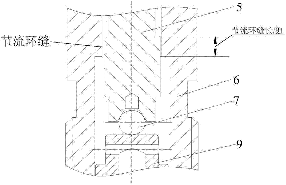
[0026] The basic idea of ​​the present invention is to propose a novel micro-flow gas mass flow controller structure, including an inlet cover, a sealing ring 1, a fastener, a spring, a valve core, a sleeve, a steel ball, a sealing ring 2, a push rod and fasten the screw nut. The 4μm-10μm radial gap formed between the sleeve and the valve core constitutes a throttling annular seam, and when the gaseous working medium enters the controller from the air inlet, the micro-flow control is realized through the throttling annular seam. The adjustment device composed of ejector rod, steel ball, lock nut, spring, etc. can adjust the position of the valve core to achieve the purpose of controlling the length of the annular seam, and realize the precise output of a small flow rate of 20μg / s~2mg / s under a specific pressure. Compared with the conventional flow controller, the present invention adopts the valve core and the valve sleeve as hole axis fit, realizes throttling control through ...


PUM


Abstract

The invention relates to a novel micro-flow gas mass flow controller, which comprises an inlet cover, a sealing ring 1, a fastening piece, a spring, a valve core, a sleeve, a steel ball, sealing rings 2, an ejector rod and a locking nut, and is characterized in that a circular throttling seam is formed through a radial clearance of 4[mu]m-10[mu]m between the sleeve and the valve core, micro-flow control is realized through the circular throttling seam after a gaseous working medium gets into the controller through the gas inlet, and accurate output of micro flow of 20[mu]g / s-2mg / s under specific pressure is realized. According to the invention, the valve core and a valve sleeve are in hole-shaft fit, throttling control is realized through the circular seam, the processing technology is simple, the reliability is high, and the anti-pollution ability is high. The position of the valve core is adjusted by using an adjusting device, the adjustment range is large, and flow output of the controller under the specific pressure can be accurately adjusted. Through adjusting the inlet pressure, the flow output range changes greatly, the flow control range can reach up to more than 100 times, and the novel micro-flow gas mass flow controller can be applicable to multi-mode working conditions of a system and occasions in which the flow of a working medium is required to be continuously changeable.

Description

technical field [0001] The invention relates to a novel micro-flow gas mass flow controller, which is used for micro-flow control of gaseous working medium, and is suitable for fields such as space electric propulsion systems. [0002] technical background [0003] Space electric propulsion technology has the characteristics of high specific impulse, small thrust, and long life. It is a hot spot and trend in the development of spacecraft propulsion technology such as satellites and deep space probes. The micro-flow gas mass flow controller is one of the key products in the electric propulsion system, and its throttling method is the focus and difficulty of the design. At present, there are three main throttling methods for domestic micro-flow gas mass flow controller products: [0004] The throttling orifice flow controller is composed of overlapping throttling orifice plates with small holes. It is not sensitive to temperature changes, and the flow rate can be adjusted by a...

Claims


Application Information

Patent Timeline
IPC IPC(8): G05D7/01
CPCG05D7/01
Inventor 张曦张鑫彬郭加利王玥鲜亚平
Owner SHANGHAI AEROSPACE CONTROL TECH INST
Learn More